Continue to Site

Eng-Tips is the largest engineering community on the Internet

Intelligent Work Forums for Engineering Professionals

  • Congratulations IDS on being selected by the Eng-Tips community for having the most helpful posts in the forums last week. Way to Go!

RMB for a pattern datum

Status
Not open for further replies.

Belanger

Automotive
Oct 5, 2009
2,449
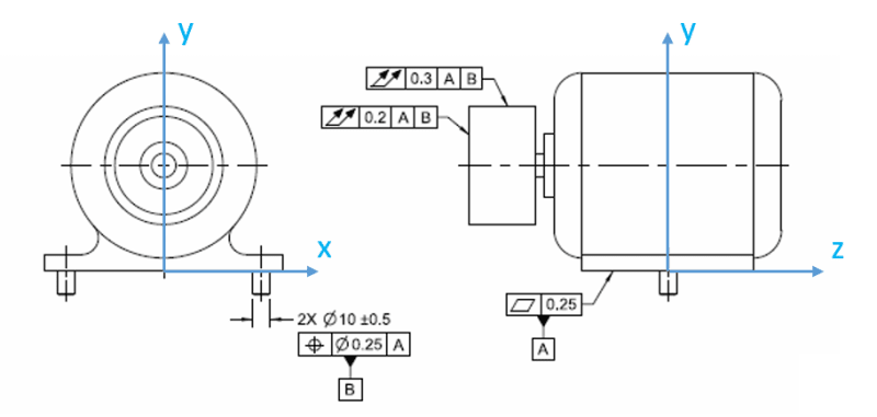
In Y14.5-2018, I notice that Figure 12-16 shows references to datum B without the MMB modifier, despite the fact that datum B is derived from a pattern of two pins. Of course runout's datum references must be RMB, but in the past we've discussed on this forum how that isn't always very practical for a pattern. Just curious if anyone else noticed that.

The applicable text would seem to be paragraph 7.12.14, but the figure referenced in that paragraph is Fig. 7-27 -- a somewhat different idea from the one I'm bringing up.

This new application of runout to a non-axial datum is one that I've heard about in the past, but any thoughts about the RMB datum in Fig. 12-16?

John-Paul Belanger
Certified Sr. GD&T Professional
Geometric Learning Systems
 
Replies continue below

Recommended for you

J-P,
Personally, I think that the bigger problem with fig. 12-16 is the selection of datum features for both runout tolerances and the recipe the committee gave us for how to interpret this.

Regarding calling out the datum pattern B RMB in that figure, yeah... one can complain about functional/practical aspect of this, but from a mathematical point of view I don't see it any more problematic than what fig. 7-17 shows (two coaxial datum features RMB establishing a single datum axis).
 
Agreed -- and notice they side-stepped your complaint by keeping at the assembly level; we've not seen that type of wording/recipe anywhere until now.

John-Paul Belanger
Certified Sr. GD&T Professional
Geometric Learning Systems
 
I am very sorry to be nosy, but (one more time just for me), I do not understand why the position Ø0.25 at wrt A primary is shown at RFS?
(I do not have your guys level of knowledge therefore I am trying learn why pos. |Ø0.25 MMC|A| was not used in this particular example of fig 12-16/ 2018 page 305)


greenimi -- They don't want the thing to jiggle at all, when those two pegs are attached to the table/assembly. In that respect it's similar to Figs. 10-5 or 10-30: No bonus tolerance.
So there's the aspect of their own position tolerances (which you're asking about), and then the fact that they are setting up the runout tolerances. Again, it's totally legal, but I just found it interesting.

John-Paul Belanger
Certified Sr. GD&T Professional
Geometric Learning Systems
 
JP/pmarc,

So I've given this some thought because the portion in 12.6.8 stating "the datum features do not establish the location of the axis of rotation, but they do constrain the orientation of the axis" really threw me through a loop. It took me a bit to suss out exactly what is meant as I think there is some nuance there between "established" and "constraint" as the datum features in 12-16 |A|B| certainly are able to constrain all translational/rotational DOF of the axis of rotation and the datum references are not modified (datum translation/customized DRF). I think perhaps this wording is misleading or at least confusing to me and would be better phrased "the datum features do not establish the location of the runout tolerance zone, but they do constrain the orientation of the runout tolerance zone" - my reasoning is as follows.

The conclusion I have come to is that in keeping with the standard's definition of runout, the scheme shown in Y14.5-2018 fig 12-16 is still closely tied to the specific use and behavior of a dial indicator during measurement. Assuming the conventions below and considering the runout tolerance on the diameter, it seems the scheme is meant to replicate fixing a dial indicator base in orientation (u,v,w) WRT to |A|B| and measuring runout of the surface of interest by traversing along (z) while rotating the feature about the axis of rotation. In this way, pure (x,y) location error of the axis of rotation does not show up on the indicator however (u,v) orientation error of the axis of rotation will. The fact that the measurement occurs fixed to a frame other than the axis of rotation while the feature is rotated about the designated axis of rotation is what creates this phenomenon.

Taking this a step further, I tried to envision how this could be replicated by a dynamic profile tolerance as dynamic profile to |A|B| would produce a different result as the location of the tolerance zone would be fixed in location/orientation fully to |A|B|. If the feature(s) which define the axis of rotation (for example the ID's of two bearings) is denoted datum feature C my first guess would be a specified 0.3 dynamic profile tolerance wrt |A(u,w)|B(v)|C(x,y)| however this wouldn't account for variations between the shaft/bearings so perhaps a note that the feature must be measured while rotating about the designated axis of rotation - the FCF could potentially be changed to show |A(u,w)|B(v)| in that case.

Thoughts?

total_runout_of_an_assembly01_ekrykz.png
 
chez311,

I agree with your assessment and with the proposed solution (dynamic profile referencing |A(u,w)|B(v)|).

I will just add that in my opinion this figure is... sadly... a great/another example of how unimportant to Y14.5 committee mathematical rigor sometimes is. Just now imagine the math committee having to find a common runout tolerance definition for regular runout applications and the assembly application.
 
pmarc,

Thank you, I'm glad you agree - it took me a little while to wrap my head around because of the way its worded in the standard.

I agree, sometimes it seems like the Y14.5 committee throws stuff at the wall to see what sticks, any attempts at mathematical/geometrical rigor be damned. That said, I guess one could argue that this is a "functional" control (ie: it "works" and can be interpreted) as long as its clear that the feature must be physically rotated around its axis during measurement no matter how its measured with a dial indicator, CMM, or otherwise.
 
I was out for several days, but thanks for the responses.
As I mentioned, this idea had been bounced around before, but the datum thing is certainly different for runout usage. Perhaps the committee will contend with how this might be similar to dynamic profile -- I'll bet it was like two ships passing in the night that never even saw each other.

John-Paul Belanger
Certified Sr. GD&T Professional
Geometric Learning Systems
 
Obviously someone has envisioned a clamp for those two pins such that when one is 1mm smaller than the other it will uniformly taper in on the smaller one while compensating for any lack of perpendicularity that might add an additional 0.5 mm differential to them.

I wonder if ASME sells these clamps in the gift shop.

To expand on something chez suggested - the example doesn't allow for rattling within the bearings; no doubt the reason for the original expectation of an RFS basis was to avoid that situation.
 
Status
Not open for further replies.

Part and Inventory Search

Sponsor