Continue to Site

Eng-Tips is the largest engineering community on the Internet

Intelligent Work Forums for Engineering Professionals

  • Congratulations pierreick on being selected by the Eng-Tips community for having the most helpful posts in the forums last week. Way to Go!

Rolled cylindrical SM part with bent flange 1

Status
Not open for further replies.

oharag11

Mechanical
Jun 18, 2015
42
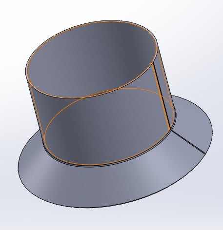
Hi I posted something in SW forum since that is what we use - though I have a general question regarding a cylindrical rolled part (large diameter) with a pre-bent angled flange along the length of the part. I attached a JPEG showing what I mean. I have to presume that rolling this part will cause large stresses along bend causing the flange to warp some. Is there a Sheet Metal expert on this site? Any other avenues I can pursue?

Thanks
 
Replies continue below

Recommended for you

Hi

There is no attachment.

“Do not worry about your problems with mathematics, I assure you mine are far greater.” Albert Einstein
 
He's double posting and expecting us to look at the other post for details.

It's a conical funnel to a cylinder tube - simple enough with rotary forming / metal spinning of particularly malleable metals, but not a "sheet metal" part. for example.
 
From past experience - the sequence is to roll the cylinder, roll (or cut) the flange separately, then weld the two together. I've done this a LOT over the years (for cylinder outside diameters ranging from 1 to 7 m, and lengths from 1 to 6 m, with cylinder thickness ranging from 100 mm thru 400 mm).

Converting energy to motion for more than half a century
 
rolling a bent angle is difficult.

forming in "O" condition then heat treating is probably also difficult.

what material ?

what sort of production run ? (ie is it worth setting up "proper" tooling ?)

you can form the flange as you roll the tube, by running the sheet metal over a die.

what industry ? "cheap and cheerful" or "money is not a problem" ?

"Hoffen wir mal, dass alles gut geht !"
General Paulus, Nov 1942, outside Stalingrad after the launch of Operation Uranus.
 
Not having seen the detail- I will point out that the people that own the equipment that can do it, will generally know what their setup can and cannot do.
Also, if you happen to be far away from said people, a major part of the expense will be getting it there and back.
A 90 degree flange bent into the edge of a plate- I think that has been done. At some other angle- less likely.
 
This is the flange:
Screenshot_2022-12-12_150058_lwne86.jpg
 
Everything works when there is no scale.

Is this a one-off or production piece?

It looks do-able as a hydroformed and trimmed part.

Could probably spinform it.

Might be able to stamp it.

Does it have to be one piece? It would be simple enough to make in two pieces and join by welding.
 
Sorry I tried uploading file.

Here is context:
- .030" (.762mm) thk Molybdenum sheet (we have a high temp requirement - 900 degree C).
- overall internal diameter 32" (814mm)
- the graphic I presented was just an FYI - design is not completed due to difficulty with SolidWorks SM.

So, this is small qnty run (at most maybe 10-50 pieces per year).
I don't think hydroform or punched will work here. Rolling seems like the best method.
Thanks for the info on the roll forming with flange forming during roll.
I thought to perform bend first - then roll - but if you can form/roll at the same time that's best option.

So, welding the flange onto the part is an option - but obviously adds cost. We also need to worry about high temp - weld cracks.

Any thoughts on creating this in SolidWorks? The example shown above I used swept flange function for SM. It seems to have worked - though I can't perform an unbend on the formed part. I can flatten the part, but I need to add holes cutouts in the flat. Any help here would be appreciated.
 
Mo, so is this TZM (or a similar alloy) or is it pure Mo?
The formability is rather different as I recall.
Give the cost of the RM I can't see the cost of the weld being a big deal.
Yes, it is tricky to weld correctly.
But scrapping one piece per year due to forming issues would cost much more.
We had a lot of welded TZM furniture in our vacuum furnaces.

= = = = = = = = = = = = = = = = = = = =
P.E. Metallurgy, consulting work welcomed
 
Ed

Molybdenum Type 361

So, the question with weld - I would still need to form some sort of mating circular flanged piece to mate to base rolled part. Still same challenges here.
 
I have seen these done by cutting the flange from flat sheet (many times welded together from smaller sheets) and then rolling a small flange on the ID. This allows for a lap or butt weld depending on your situation.

= = = = = = = = = = = = = = = = = = = =
P.E. Metallurgy, consulting work welcomed
 
how much load is going through the flange ? could you roll the tube, weld seam; cut flange from a flat sheet (so it looks like a circle), and weld onto the end of the tube ?

From the flat circle flange idea ... bending a small flange to match the tube doesn't seem to be too hard ?


"Hoffen wir mal, dass alles gut geht !"
General Paulus, Nov 1942, outside Stalingrad after the launch of Operation Uranus.
 
it really depends on which vendors and their equipment or what internal forming machines are available. this can be done, but the production volume will dictate the process
 
So, my only thoughts on just welding a flat flange onto the end of the cylinder (as opposed to having a mating overlap flange as proposed above) would be due to high temp (900 degree C) causing weld cracks, but the entire inside our device is under a vacuum so there are downward forces being exerted on the rolled SM part.

Thanks for all the advice - does anyone here use SolidWorks - and have a way to create this part. The part that is displayed is using swept flange about an axis. It looks good - I can flatten it - but I can't add an unbend - so no way to add holes on faces for other parts to attach to base part.
 
In CAD "sheet metal" means - constant thickness and single-radius bends in one direction. Basically, it's only considered sheet metal if you can make a piece of paper form the same way without wrinkling or tearing.

At the least the fillet is a bend in two directions. See and note that a cylinder and flat plane have zero curvature, which is why you can easily roll a flat sheet into a cylinder. The fillet has a negative curvature and requires deformation of the metal to form. This video has a more interesting discussion (caution: video may induce feelings of hunger) In combination the cone and cylinder form a composite that is also relatively toroidal, so the combination is also not zero curvature and cannot be formed from a flat sheet without deformation.

Some software, like SW, will stretch (pun!) the definition and create desperately faked "flat" patterns that cannot realistically be used for anything other than a first cut rough approximation of the material to be used. To do a reasonable job requires an FEA model to map the stretch, shear, change in local thickness, and sometimes local work hardening. On top of that the conversion of the flat pattern to a compound curvature part is highly dependent on the method used (skilled worker, die forming, stamping, hydroforming, et al. Each requires a different "flat pattern."

If there is a problem with "sheet metal" software in defining the part then it's often a part that is not created with sheet metal processes that preserve material thickness. It's often like looking at a vacuum formed part and deciding what that flat pattern is like - hint: no matter the final shape the flat pattern is a much larger sheet, usually a rectangle, that is flat.

There should be no cracking due to welding just because the part is used in a hot environment. There might be cracking because the part is not uniformly heated, causing high stresses in the area of the stress concentration where the two sections meet. This can happen if the part is welded or formed.
 
Thanks 3DDave. I figured as much - I did realize that there would be deformation along the radii for formed flange.

So the method I used in SW - swept flange - though can be flattened using SW tools - would be inaccurate in where the bend line is situated - correct?

Are there any CAD solutions that can do this part? I know you can use die punch for some features (louvers/locating bumps etc...). Some higher end Cad solutions have a number of advanced tools for manufacturing different end parts.
 
Forming that conical flange with a flange-tool will see a large reduction in thickness - I'd estimate 30-50%.

Any flat pattern has the potential to be inaccurate everywhere on that part.

As I suggested - try cutting out flat paper and forming what you want.
 
Status
Not open for further replies.

Part and Inventory Search

Sponsor