Eng-Tips is the largest engineering community on the Internet

Intelligent Work Forums for Engineering Professionals

Roller bearing mechanism problem 4

Status
Not open for further replies.

MH500

Industrial
Aug 26, 2016
34
0
0
IR
Hi every one
Recently I tried to make a Laminar box that composed several layers. and layers must have moving freedom in X (Longitudinal) direction under load.
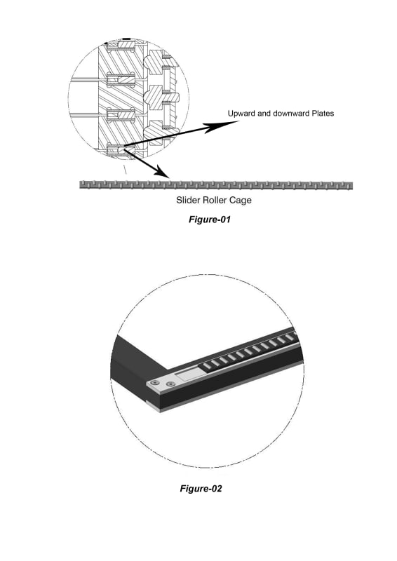
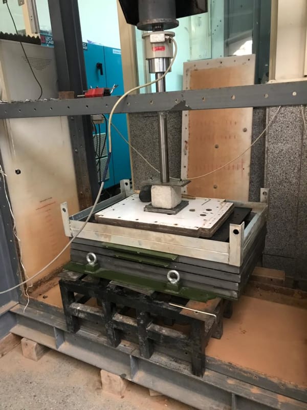
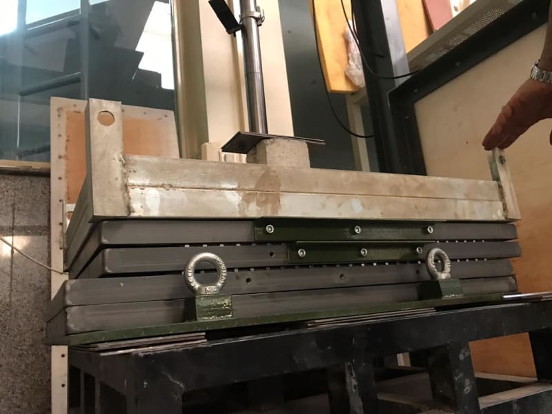
to reach this goal I made some Aluminium frames and put flat bearing between layers.
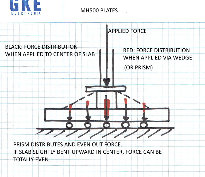
But when I applied load on frames, they Locked and didn't move at all .
why this happend ?
a9e53393-2ae3-4ddb-8d5d-09537bee4a83_d9djd8.jpg
 
Replies continue below

Recommended for you

These are rolling pins? How are they held in position? There's either too much friction or they are out of alignment or they are elastically or plastically deforming the aluminum would be my top 3 guesses.
 
Yes
They are roller pins that stayed in positions with a cage.
The 2 surfaces in upside and downside of pins are Ck45 plates that we grinding them. so rollers don't touch Aluminium surface and I didn't see any deformation after loading.
How can I find that friction is reason ? and how decrease friction ? because lubrication didn't solve my problem.
 
There is elastic deformation as the rods are flattened and the plates are dented. This will not be permanent so it won't be seen after the load is removed. Since it is a function of the elasticity of the materials involved there is nothing to change to fix it with the current components.

Rolling resistance decreases with increasing roller diameter. Making the rollers larger will decrease the friction.

Since the amount of rolling resistance is not proportional to the load, dividing the load by the number of rollers and then summing the individual contributions will be required. Finding the exact distribution will probably require an FEA process since it is clearly not going to be uniform with the given apparatus. Alternatively, one might suppose all the load is on one roller and set that as the upper limit.
 
Thank U
first of all, I've already analysed the assembly and theoretically It shouldn't deform under load.
Increasing the diameter of rollers in order to decrease friction, was a good point. but my priority is using provided rollers because I cant buy a new one.
By the way I've decided to change the prior design (Figure-01) to new one (Figure-02).
What do u think ?
Cat it solve my problem ?
Untitled-2_muuu7u.jpg
 
I have been working with 3D coordinate measuring machines. We used air bearings. They are stiff and can take a surprisingly high load. And have no friction at all.
The plates need to be true to avoid uneven air outlets. But some "waviness" can be tolerated. And usually countered by increasing air pressure. In CMM:s, we used something like 200 mBar and since normal pressure air is 7 Bar, you seem to have enough margin to handle 0.1 or 0.2 mm waviness. Probably more.

Gunnar Englund
--------------------------------------
Half full - Half empty? I don't mind. It's what in it that counts.
 
The Air bearings are so reliable but so expensive . furthermore, they need Air power supply.
for this usage ,they are not economic.
Thank U
 
absolutely you right.
So Whats your suggestion ?
How can I reduce the deformation in this mechanism ? because it seems that friction and deformation are 2 principal reasons to lock the layers.
Also I have weight limitation (It shouldn't be heavy)
 
Since all formulas indicate the rolling resistance is related to the inverse of the roller radius, then increasing the roller radius is a reliable method to reduce the force required - rail car wheels, for example, reduce the ratio to about 0.001 such that a 1000 unit weight requires only 1 unit of force to move.

One thing not specified is whether this ever rolls freely and how much force is required to get it to roll with the load on it. From the looks of it I think a lever could be used to apply enough force that the middle plate will move. Maybe the plates aren't perfectly flat with perfectly parallel faces or the load is more heavily applied at one end, making a semi-conical motion that is somewhat self-locking.
 
Do you have a low friction retainer/cage to keep rollers apart and their axis parallel? Rubbing rollers or nonparallel axis could cause high friction or jamming.

Walt
 
I used Textolite for cage and It has very low friction coefficient. but a little nonparallel may be one causes.
The maximum applicable load must be 55 Kn, but the layers locked under 10 Kn.
I tried to distribute the load on all over surface uniformly as I could.
These layers are Under hydraulic press. under pressure , as you said, the middle layer must move smoothly (that not happened !)
It seems I have no choice except increase rollers size.
If there is other way to solve the problem ,I`ll glad to hear that.

Thank you
 
Have you tried to measure layer pull force versus press force? You may find that you are close to your goal or not even close. Have you considered roller with axle bearings as shown here:

What is the slider movement distance as a fraction of the length? It can't be too much or the bearing support are will decrease, and the load per bearing roller will increase. Have you considered a linear recirculating ball slide scheme?

Walt
 
Another point worth considering is the load distribution across the plate. The picture looks like a system with force (the plunger) hitting the plate centrally. That will not distribute load evenly across all rollers. And you just need the roller with the highest force to stick in order to make the whole thing stick. I would try and even that out by applying force via a triangular (and possibly slightly inward curved bottom) member between plunger and plate.

Gunnar Englund
--------------------------------------
Half full - Half empty? I don't mind. It's what in it that counts.
 
The layers should be close to each other (about 5 mm) . because of that I can not use swivel skates,Linear guides, or something like that.
Although may be the force doesn't distribute complete uniformly, but I think It shouldn't cause of full lock. Because I tried to don't let that happen.
All the all your point is considerable and a'll try to correct that.
Now the problem is : Is this design wrong or not ? And if yes, how should I correct that ?
 
MH, this is what I meant:

ENGTIPS_MH500_SLAB_WITH_FORCES_1_fcfcug.png


There is a lot of space above the slabs. A force distribution element (does not need to be massive) can help eliminate the local force concentration.

Gunnar Englund
--------------------------------------
Half full - Half empty? I don't mind. It's what in it that counts.
 
I know what's your mean.
The plate that putted on top of first frame is solid .In addition,I putted some added plates to distribute the load.
However the uniform loading mighit not obtained. But differences are very low.
In the other hand, even in this state It shouldn't lock the frame. It may move hardly.
If I can find that how correct the designation, in next test I'll work better on distributing load.
Now I'm afraid the designation,may be wrong.
 
The other consideration is that whatever rolling resistance there is will be doubled because the rollers are on both sides.

I still expect the middle plate to move even under the load. It's cheap to get some 1 inch or larger black pipe and cut 4 pieces, two on each side, and try that to see what happens. I've seen black pipe used to move very large machines with little effort over imperfect concrete floors. It's the material used for home natural gas piping and is cheap.
 
Status
Not open for further replies.
Back
Top