Reno1986
Civil/Environmental
- Sep 19, 2019
- 11
Hello,
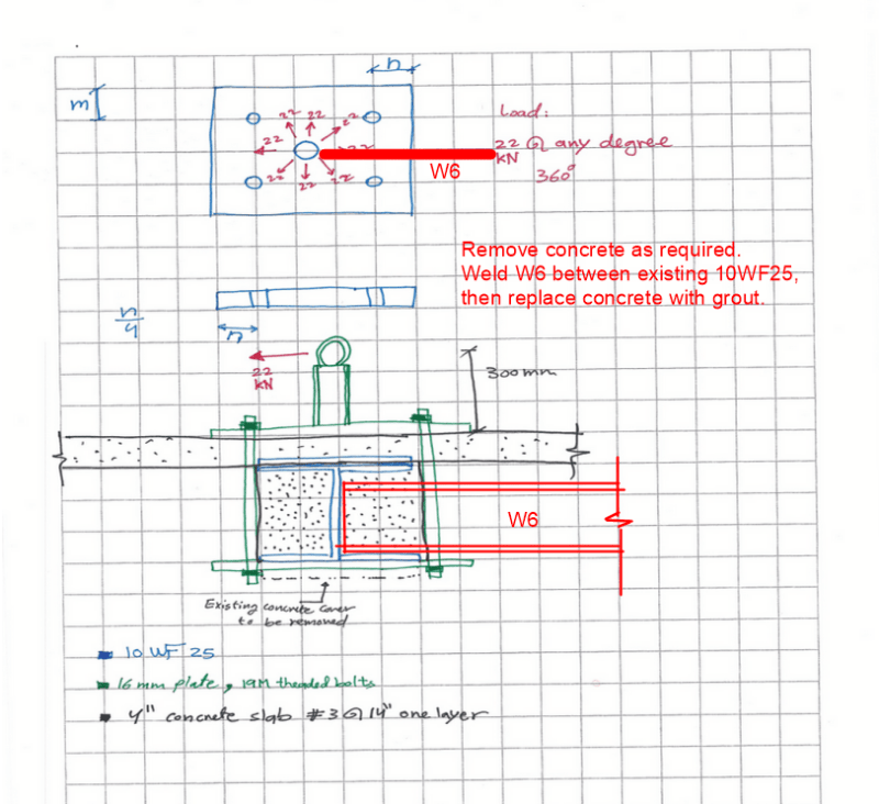
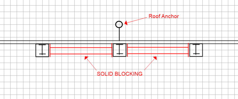
I have to provide a design for a roof anchor on an existing composite slab roof. The building is old and the floor system consist of 4" slab with #3@14" and 10WF 25 steel beams carrying the slab along the 5.3 m span connected by four bolts connection to the existing steel columns.
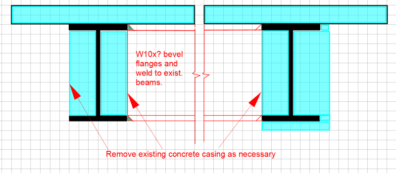
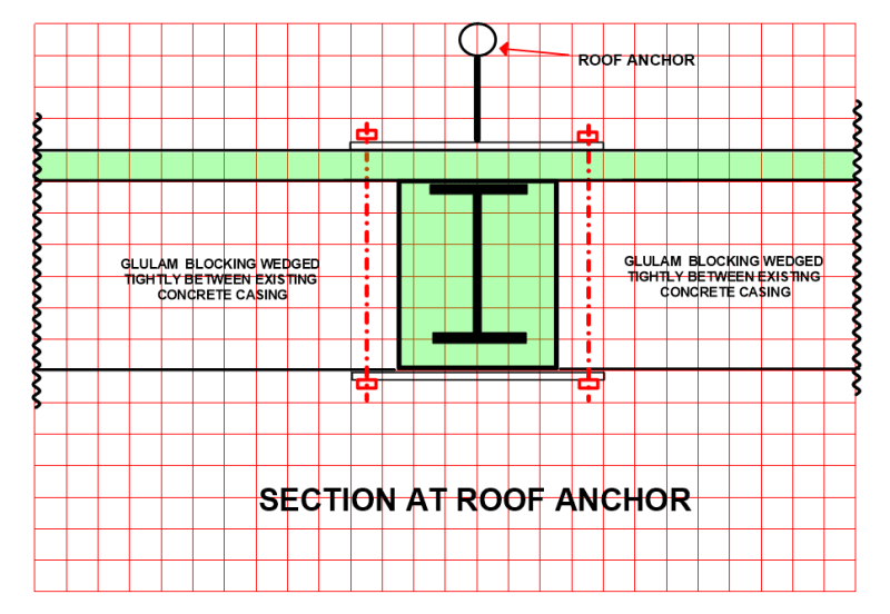
The steel beams are fully encased by concrete and not visible.
My thinking is to provide a connection similar to what it will be on a steel deck new construction design.
The connection will be steel plate with four anchor M19 and clamping the bottom flange of the steel beam. After removing the cover on the bottom flange the steel plate will be placed under the bottom flange.
The design force is 22 kN applied at a hook elevated 300 mm from the top of roof slab and within any degree at the hook.
I would like to confirm the required checks for this design:
As a starting point the existing beam with the applied loads takes the 22 kN load where I applied at the end of the first third of the span upward and downward.
Check of bottom plate bearing on the bottom flange
Check of upper plate bearing concrete slab, (Would grout pad be necessary?)
Shear and Tension on bolts
Bearing pressure on bolts hole and bolts
Other than that I found that the generated moment could cause torsion on the beam below which I am planning to check but would not the concrete casing restrain that ? and how I might assess that?
Any thoughts or comments are appreciated.
sketch is attached
Thanks,
I have to provide a design for a roof anchor on an existing composite slab roof. The building is old and the floor system consist of 4" slab with #3@14" and 10WF 25 steel beams carrying the slab along the 5.3 m span connected by four bolts connection to the existing steel columns.
The steel beams are fully encased by concrete and not visible.
My thinking is to provide a connection similar to what it will be on a steel deck new construction design.
The connection will be steel plate with four anchor M19 and clamping the bottom flange of the steel beam. After removing the cover on the bottom flange the steel plate will be placed under the bottom flange.
The design force is 22 kN applied at a hook elevated 300 mm from the top of roof slab and within any degree at the hook.
I would like to confirm the required checks for this design:
As a starting point the existing beam with the applied loads takes the 22 kN load where I applied at the end of the first third of the span upward and downward.
Check of bottom plate bearing on the bottom flange
Check of upper plate bearing concrete slab, (Would grout pad be necessary?)
Shear and Tension on bolts
Bearing pressure on bolts hole and bolts
Other than that I found that the generated moment could cause torsion on the beam below which I am planning to check but would not the concrete casing restrain that ? and how I might assess that?
Any thoughts or comments are appreciated.
sketch is attached
Thanks,
![[pc1]](/data/assets/smilies/pc1.gif "[pc1] [pc1]")