Continue to Site

Eng-Tips is the largest engineering community on the Internet

Intelligent Work Forums for Engineering Professionals

  • Congratulations KootK on being selected by the Eng-Tips community for having the most helpful posts in the forums last week. Way to Go!

Roof Compression Ring

Status
Not open for further replies.

Thibbs

Structural
Jan 29, 2006
6
Hi All,

I am reviewing a church that has a square central area that is 40'x40'. In from each corner of the square, there are hip rafters which form a peak. I am comfortable designing this with a tension ring base of the roof to handle the thrust.

The architect now wants to add a 6'x6' cupola by cutting off the peak. I've researched the concept of compression rings at the top but can't get much information on the design/detailing. I've seen many "compression ring" photographs however my compression ring will be a square.

I'm in a hurricane zone and I'm generally concerned about unbalanced loads from wind and the torsion/twisting that this ring will be subjected to. The architect is open to us using structural steel.

Can anyone shed some advice on suitable reference material.

Thanks
 
Replies continue below

Recommended for you

I worked for a company that builds "round" houses and buildings - actually anywhere from 8-22 sides, with the overall effect being round. Their roof system uses a compression ring and tension collar system at the center with essentially a half-scissor truss creating the roof. The calcs were done by the in-house engineering staff. It's pretty straightforward math when done using a circle.

That being said - could you create a round compression ring and tension collar system, with a square overbuild?

Good luck!

Please remember: we're not all guys!
 
Whether a square ring is in tension or compression, it is unstable without at least one member joining diagonally opposite corners. The small 6'x6' compression ring could be stabilized with moment connections at the corners but the 40'x40' ring may present a more difficult problem.

If the roof deck acts as a diaphragm, it is possible that both rings can be stabilized by the deck. Offhand, I know of no suitable reference material.

BA
 
Thanks.

SLTA.....I'm not sure how straightforward the analysis is whether it is a circle or a square particularly with unbalanced load. Seems relatively complex and would need 3d analysis to capture the all the in and out of plane effects.

BA.....there are enough walls at the base of the roof in each direction that I can use as shearwalls to stabilize the base. The top ring can be in either tension or compression due to the wind loading. I like the idea of moment connections. Is there any merit in making a top ring a truss like you see in sports stadia? Is it done primarily to take out local bending from the ring or is it essential for other phenomena? I know my ring is small but would like to understand the principles better.

Thanks.
 
I've encountered this with both large skylight frames, where there was no diaphragm, and outdoor pagoda structures where there was. Here's what I've got:

1) If you've got a tension ring (rectangle) and four rafters that meet at a common point, I believe that the system is stable, even under unbalanced load, so long as there is vertical restraint at the bottoms of the rafters.

2) If you lop off the top of the pyramid as you're proposing, the name of the game basically becomes reconstituting the restraint that you had up there when it was a nice, concentric, pinned connection. The four critical issues for the compression ring-square become as listed below.

2a) Being strong enough for the balanced load, pure compression case. This is pretty easy.

2b) Keeping the ring-square from racking in plan under unbalanced load.

2c) Keeping the ring-square from pitching about a horizontal axis like teeter totter.

2d) Keeping the ring-square from rigid body rotating about a vertical axis in the center.

3) Without relying on a diaphgragm, 2b can be resolved by creating moment connections in the ring-square joints about vertical axes through the joints. An improvement would be to install an x-brace across the ring-square but that is often unnecessary and can compromise architectural design intent.

4) Without relying on a diaphragm, 2c can be resolved by creating moment connections between strong axis flexure in the ridge rafters and the ring-square AND providing torsion connections between the four members of the ring-square. Often times, making the ring-square from HSS makes sense for this reason.

5) Without relying on a diaphgragm, 2d can be resolved by creating moment connections in the ring-square joints about vertical axes through the joints AND creating nominal moment connections between the weak axis of the rafters and the ring-square.

6) Creative use of your structural diaphragms, when present, can take care of 2b, 2c, and 2d if properly designed. For modelling it can be convenient to treat the diaphragms as equivalent cross bracing in each of the roof planes. If you're going to rely on your diaphragms in this way, some consideration for erection safety and stability is in prudent. It might make sense to cross brace the ring-square and/or the roof planes temporarily. Or use temporary props.

7) One design strategy is to design your compression ring-square to deal with the maximum balanced load compression but then rely on diaphragm action for any imbalances.


I like to debate structural engineering theory -- a lot. If I challenge you on something, know that I'm doing so because I respect your opinion enough to either change it or adopt it.
 
If you do not wish to rely on the deck to provide diaphragm action, then trussing could be used in each of the four planes of the roof.

BA
 
Thanks Kootk for the detailed response and BA for your thouhts. I imagine that once the 4 points noted (2a-2d) above are resolved, you consider the overall structure stable.

I'm comfortable with the balanced condition. In the unbalanced case where you have an uplift on one side of the ring and downward force on the other side, as described in 2c of your post, even with the moment connections between compression ring and rafter, the whole structural support for the vertical load seems cylical and unstable withot a moment connection at the base of the rafter.

I like the idea of providing a truss in the plane of the roof diaphragm and have attached a partial roof plan and building sections showing this. Can I simply analyze the truss in 2d twice for each load component. First analysis in plan to handle the lateral load, second analysis in section to handle the vertical load and then combine the forces to design the members of the truss? That way I would ignore the compression ring completely. I'd like to resolve the loads simply by hand before I do a 3d model to understand the load paths and can then use it to check my model outputs.

My other thought was to add a knee brace at the the valley rafter locations subject to the architect's approval.

Thanks for all the help.
 
 http://files.engineering.com/getfile.aspx?folder=5ee974bc-9646-4582-b516-e92617624806&file=scan0002.pdf
a while back I worked through a wood framed square pyramid roof with a tension tie and satisfied ( or fooled?) myself that is was stable even with snow on 1 or 2 or 3 sides. As I recall I looked at it as 2 intersecting 3-hinged arches.
a diagonal section of your architect's system presents a 4 or 5 hinged archish thingamabob, hence moment connections et al.
wondering if you retained the full length hips for 3 hinged arch action and provided beams near the peak in a 6' plan square to support cupola, and skylight the top three feet of triangles to let the light in from the heavens above
 
Thibbs:
What does the cupola really do? Is it ventilation, does it have windows, so it has to stay open at the underside? With the ridge beams meeting the cupola half way up its four sides, this kinda minimizes the windows. Could the four valley beams still run up to a peak, at (along with) the ridge beams? Then, you end up with a ring which is a heavy walled pipe (or 8 sided, fabed. HSS) large enough in dia. to accept all eight beams. What is the roof sheathing (diaphragm) system, and why can’t it be used? I don’t see the three pinned arches; the ones at the RC shear walls are rafters from the shear walls to the ridge beam, aren’t they; and the ones once removed better have some bottom chord tension ties or some mighty husky cantil. RC columns. Your blue bracing leaves something to be desired, in that there is not much triangular action and it doesn’t go to or from any points which are very solid. Mightn’t you be better off to run blue braces from the ridge/cupola joints down to the “L” shaped RC shear walls, parallel to the valley beams? You might also gain something by having your upper ring structure being two tiered, that is, one sq. ring at the valley beam connection elev. and a second sq. ring being at the ridge beam elev., and that whole frame being a rigid frame. However, the mis-scaling, bad proportions of your sketches may make the whole system much shallower than I am imagining at the moment.
 
replied to OP before I observed your sketches.
tricky...
looks like overall plan is cruciform, all open volume, with innermost square constituting open pyramid formed by valley rafters and capped by cupola approximately 2' below ridge lines, correct?
i'd still look at running valley rafters to ridge point connection...6" thick members intersecting in 6' square may look cool and acceptable to archt, and might considerably simplify and economize framing. treat as 2 diagonal intersecting 3 pinned arches similar to your other 3 pinned arches forming your innermost square....BUT...see below... ridge beams could end at side of cupola and be supported by posts from cupola support beams....
BUT where it gets tricky and design may falter is if one or several of the 4 side hallways are loaded and others not...my concern being that the tension force induced on the (say) one tension member supporting that 3 pinned arch (the tension member that is loaded both by the 4 sided pyramid and also the building hall/wing) may throw the structure out of whack. as I understand it, the tension members naturally resolve themselves in an unbalanced simple pyramid structure. it's not obvious to me what will happen in a pyramid with four wings which share the same tension ring... i'd have to study that quite a it.... concerns me as i think about it. i'd study this particular condition quite thoroughly first.
 
This would eliminate the need for either a tension ring or a compression ring in the central space. It would require a minor, and altogether rational, architectural compromise on the profile of the ceiling beneath the cupola.

IMG_0397_m9xapt.jpg


I like to debate structural engineering theory -- a lot. If I challenge you on something, know that I'm doing so because I respect your opinion enough to either change it or adopt it.
 
Thanks for the responses all.

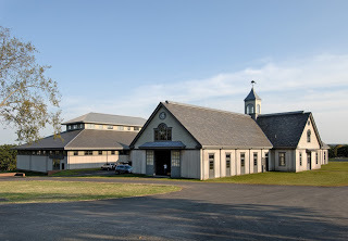
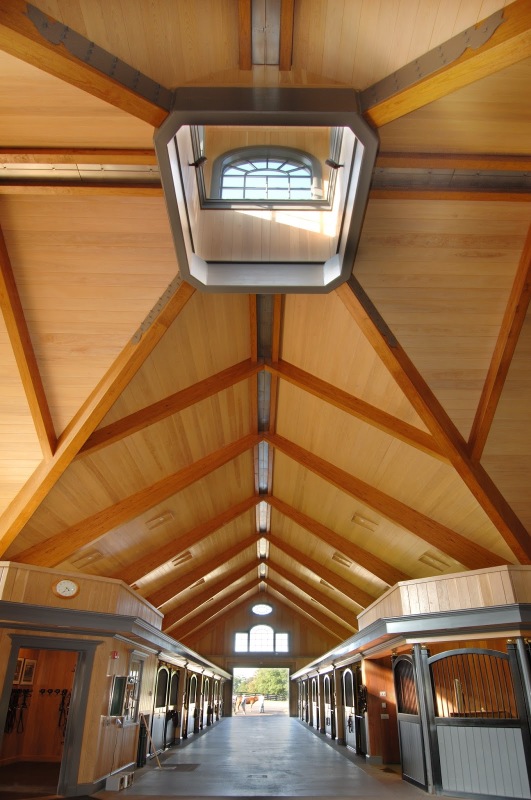
I've attached a couple of pictures which is perhaps the architect's inspiration. Can help others visualize the problem better since my sketches and description may not have been clear. The only difference is I am proposing purlins over the three pin arches and the ceiling will be to the underside of the steel beams hiding the structure.

Kootk....I don't understand your framing. Can you explain in greater detail how the cyclical nature of the support system is stable?

Triangled and Dhenger.....my first suggestion was to leave the rafters running through but that didn't fly. If I end up with problematic 3-pin arches then I will suggest adding steel columns to make a portal frame.

BA....your bracing certainly looks cleaner and looks to more efficiently restrain the compression ring from racking due to horizontal load. I'm still having difficulty resolving the vertical load in your sketch. Looks like your framing is still heavily dependent on the compression ring or are you suggesting I add a steel ridge beam that cantilevers out to support the valley rafters?

I love the feedback......thanks to all.
 
 http://files.engineering.com/getfile.aspx?folder=5e72e9a0-3040-4769-b382-fd068f312937&file=DSC_8515.jpg
DSC_8515_uejrhb.jpg


For those who don't like to download attachments.
 

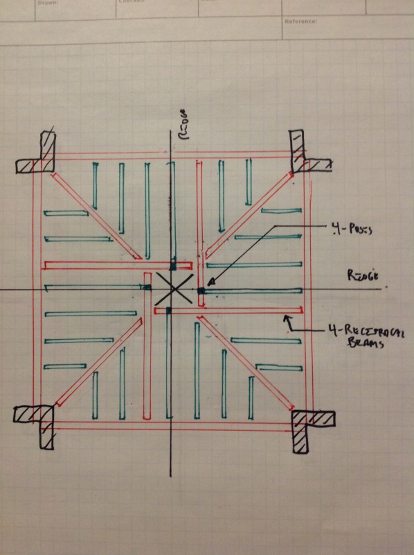
It's essentially a version of a strong axis moment connection around the opening. Plenty of precedent: Link. Vibrations can be weird so it would require careful consideration in a floor. For a roof, though, it's just ponding which is pretty easily modelled/evaluated. You could also just run two of the beams right across and ditch the reciprocal business. That seems less elegant however.

The system in the photo is gorgeous. I'd guess that's an an HSS frame with moment/torsion connections every which way and relying on diaphragm action for unbalanced load as we discussed at the top.

I like to debate structural engineering theory -- a lot. If I challenge you on something, know that I'm doing so because I respect your opinion enough to either change it or adopt it.
 
nice read KootK, thx.
last nite I thought it was the beer talking to me
 

Thibbs said:
BA....your bracing certainly looks cleaner and looks to more efficiently restrain the compression ring from racking due to horizontal load. I'm still having difficulty resolving the vertical load in your sketch. Looks like your framing is still heavily dependent on the compression ring or are you suggesting I add a steel ridge beam that cantilevers out to support the valley rafters?

I was trying to come up with a stable shape 40'x40' in plan, similar in principle to a truncated pyramid. The compression ring forms a necessary part of that shape. I believe the shape is stable for loads applied in any direction but I could be mistaken.

Alternatively, four cantilevers are possible but instead of cantilevering the ridge beam alone, one could cantilever the deeper section including the ridge beam and the valley beams, picking up the cupola at each corner but that would entail additional bracing members in the plane of the roof outside of the 40'x40' square.

BA
 
Status
Not open for further replies.

Part and Inventory Search

Sponsor