Continue to Site

Eng-Tips is the largest engineering community on the Internet

Intelligent Work Forums for Engineering Professionals

  • Congratulations GregLocock on being selected by the Eng-Tips community for having the most helpful posts in the forums last week. Way to Go!

Roof Truss Design 2

Status
Not open for further replies.

alaguengg

Structural
Jun 11, 2020
5
Dear All,

I am designing a roof truss 16m span, a howe truss for a pre engineered building. (Attached Model image) In seismic analysis, I am getting a minor axis moment which is governing my top and bottom chord design. I already braced the budling. Kindly enlighten me to get rid of these minor axis moments.

Thanks
AR
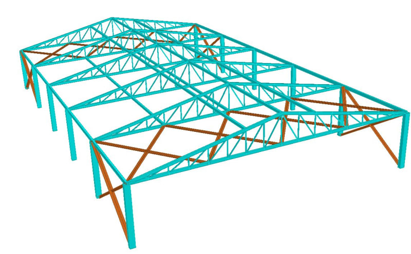
Model_akwwr2.jpg
 
Replies continue below

Recommended for you

Not sure if I understand all of your issue, but:

1) Minor axis bending of the top chord will likely be resisted by the roof purlins, which may not be included in your model.
2) Minor axis bending of the bottom chord will be resisted to some extent by the struts between the end bay bracing trusses. Perhaps you need additional struts, or fly braces.
3) You show side wall bracing in the end bays, but no bracing across the building. Are those trusses supposed to act with the columns as moment resisting frames for lateral loading? With no depth at the truss to column connections, it is hard to see that happening.
 
Thanks for your response pal.

The end connection is moment resisting connection. I will increase the depth of truss at the ends. The model shown is preliminary.

with the across bracing at the end bay will help to reduce the minor axis bending??

Thanks in advance.
 
Why is your lateral bracing at the bottom chord level of your trusses? Shouldn't this be on the same plane as the top chord to help provide diaphragm action?
 
@StrctPono, Purlins will do the job of bracing at the top chord and in order to brace the bottom chord, the struts are provided. Thanks.

@MIStructE Pal, Could you please be elaborate on what ways it could be unstable. Kindly help.
 
In the long direction - your top chords are not braced back to anything. I would expect to see a top chord wind girder, or at the very least some diagonals tying the top chord Longitudinal ties you have modelled back to the bottom chord wind girder. You suggest that the purlins will do the job? What are they braced back to? What is restraining the truss compression chord? Are you relying on diaphragm action of the deck?

In the short direction - you have no roof bracing, no wall bracing and that frame will not act like a portal given the pure pinned Connection between truss/column.

I say all of this assuming of course that you don’t have fixed bases and cantilever columns as you haven’t mentioned this. Is this the case?

Assuming pinned bases, I expect that your model is throwing up all sorts of minor axis and torsional moments as it tries to stabilise itself. Forget seismic for now, apply some lateral wind and I expect the deflections are wild.


It is common to use a knee brace in a post/truss system to create a moment frame. If your plan does not permit a knee brace you will need to go back to the drawing board, use very large wind columns, or design the truss/posts to behave as a moment connection. I agree you have a stability issue right now.
 
If you think the trusses are braced by the purlins as configured and didn't see an issue with zero depth trusses at the columns, you don't understand stability and you need to see out an experienced engineer from whom you can learn the basics.

Don't look to software to correct the poor application of engineering principles.
 
I suggest to perform a plane truss frame analysis for lateral load, one each on the plan of top chord and the bottom chord, assuming simply supported on the columns. I guess you may find your model is in between just fine and a little over design. There are certainly rooms for modification, and could have many more suggestions, but without carefully study the model, all efforts are waste of time. Weak axis bending alone is not the problem, problem lies in combined bending (My, Mz) and axial force, if present.
 

Can you elaborate? As below?

I'd use a beam and post system in the endwalls and not trusses... else it may be difficult to transfer wind loads to the roof diaphragm.

Dik
 
alaguengg,

Looked much lighter, how's analysis worked out? And, is the bottom chord X bracings in middle-bay are necessary?
 
Animate your model and see where it moves. That will help you decide. You don't have enough lateral bracing in the truss frame/plane as hokie66 noted.

 
Outside the overall stability issues it looks like you are running STAAD, in that case every node will get a porpotional lateral load in the sesmic case. So you will see weak axis bending in the top and bottom chord.
 
retire13 said:
Looked much lighter, how's analysis worked out? And, is the bottom chord X bracings in middle-bay are necessary?

Looks like he is using that to brace the bottom chord purlins which, ideally, are bracing the endwall hinge.
 
Do Ron suggested model check to spot weakness.
 
Retired13,
Bottom chord bracing are to brace the bottom chord purlins. Is there any other way to restrain the bottom chord movement during a lateral load?. Please advise.

dik,
Actually, Now I tried the same span without truss, with beam frames. It is giving lesser weight than Truss arrangement. In portal frame arrangement stability is much higher it seems. But in trusses I dont know the ways to improve the stability of system.

Ron,

In longitudional direction, movements are less. In transvesre mopvement is maximum. If Transverse bracing is no feasible as per site requirement. Then incraesing the column size is the only option??

Ideem,
Still I am getting a little amount of Minor axis bending. in Truss top & bottom chords.

dick head,
as of now, all welded connections except at the bracings

 
Some minor axis bending is to be expected in a 3D model like the one you posted earlier.
 
Status
Not open for further replies.

Part and Inventory Search

Sponsor