Continue to Site

Eng-Tips is the largest engineering community on the Internet

Intelligent Work Forums for Engineering Professionals

  • Congratulations waross on being selected by the Eng-Tips community for having the most helpful posts in the forums last week. Way to Go!

Root cause analysis

Status
Not open for further replies.

fmc2001

Mechanical
Jan 5, 2016
11
Hi everyone.

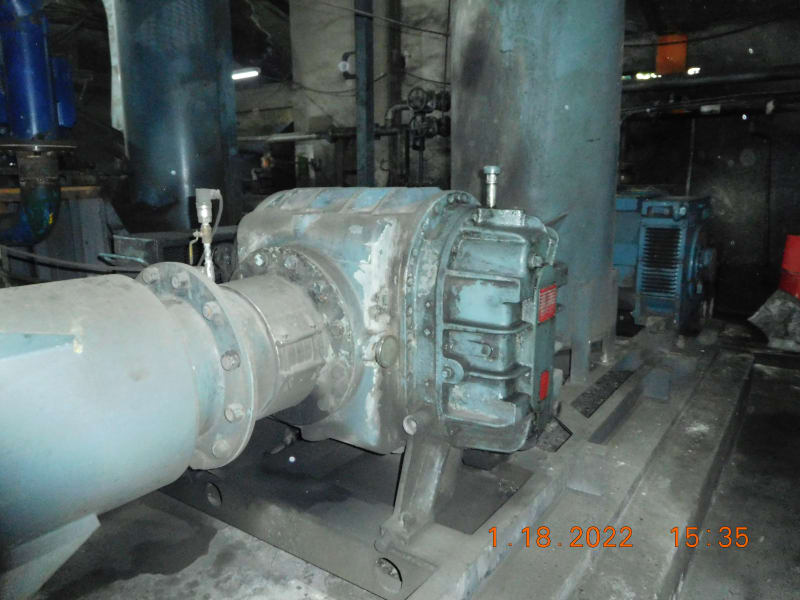
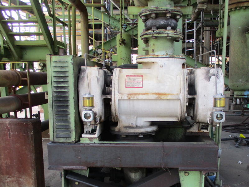
I would like to consult for a blower that was recently repaired? I would appreciate any help on this.

Attached document is my initial investigation of the blower and hopefully you may take time to read this. On the last pages of this presentation are only my suspicion. I haven't included the integrity of the Allen cap screws but would also send this for a shear test and tensile test for verification. This blower is driven by a 250hp motor/4160voltage. Blower speed is 1565rpm. I would really need any expert advice on this matter.

I would appreciate any help on this please.

Thank you very much.
DSCN8716_dmywxk.jpg


Sincerely,

Whispair guy (fmcseals)
 
Replies continue below

Recommended for you

Do you have an explanation for the corrosion of the flange bolt in slide 14?
 
My feeling is that some object jammed between the rotor lobes at start-up. You seem to be suggesting that this was due to over-pressure due to a blocked discharge. I think if it was over pressure the cracks would have separated completely due to the stored energy of the gas pressure. However, if something jammed, there would be evidence found, unless it was concealed by someone.
 
If you look closely there are also indications that the rotor contacted the end plate.

Screenshot_20220418-210751_zqf4jq.png
 
Roots blower in coal fines / air delivery. Strange then that you have an inlet filter on the schematic on slide 7 - how is this supposed to work then? - that filter would bung up in no time at all.
Given the very small gaps between the lobes in a roots blower, am not surprised this blower has failed in abrasive coal fines service. The roots blower I worked with many years ago was in plain (clean) combustion air delivery service. Wouldnt a centrifugal blower be a better choice here ( typically used in fines laden hot exhaust fumes service), or is the required dp of 9.2psi too much for a centrifugal option?
 
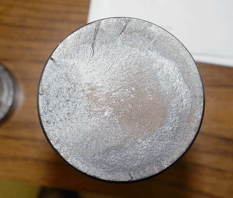
I have experienced similar failures on similar machines. Our blower is a bit smaller than yours and has some important design differences. In our blower (also in lift gas service), the drive shaft is machined integral with the rotor and made of ductile iron. We overhauled the blower and replaced the rotors with new ones. The drive shaft snapped off within two weeks. The fracture surface was indicative of high cycle fatigue in bending.
Capture_zonwzx.png


It was caused by a machining error that introduced a stress concentration at the intersection of the input drive shaft and the rotor body. The alternating stress came from the belt drive which had been converted from V-belts to cog belts.

Capture_jhwdhp.png


I suspect a problem with your belt drive that overstressed the connection between the drive shaft and the rotor: belt tension, eccentric sheave, belt alignment, etc.

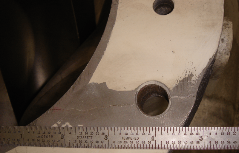
Our machine also had various cracks that may have been unrelated to this particular failure.

Capture_j3fill.png


Our lift gas blower experienced another failure when the inlet bag filters failed and catalyst dust plugged up the machine.

Johnny Pellin
 
Hi Everyone.

Thank you for taking time and sharing your thoughts about my project repair for Whispair Roots Blower.

I forgot to include in my report that on the 1st and 2nd trial during operation of this blower we decided not to couple the discharge port to the silencer and operate this with an open port just to inspect, feel, hear and see if the blower operates freely without any rubbing on the cylinder housings and lobes on each other. The cylinder body's maximum temperature reading was only 40Deg C and the drive end bearing temperature max was only 82 Deg C. The rest of the surfaces of the blower reads only 35 to 40 Deg C....so far it was perfectly operating until the they decided to shut it down in the evening as the central control noticed that there was a sudden drop of amperage during the night and decided to operate the parallel unit or back up unit. To which I don't know yet the time when they decided to couple the ports to the silencer and start conveying the fine coal on the downstream where at the moment how much time was it running while coupled to the silencer and a sudden drop of amperage is noticed.

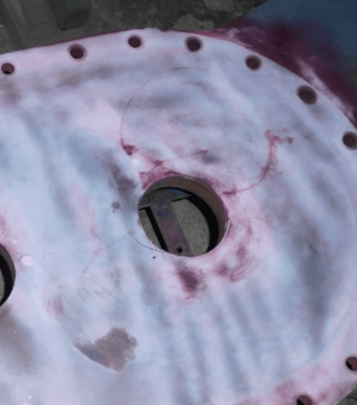
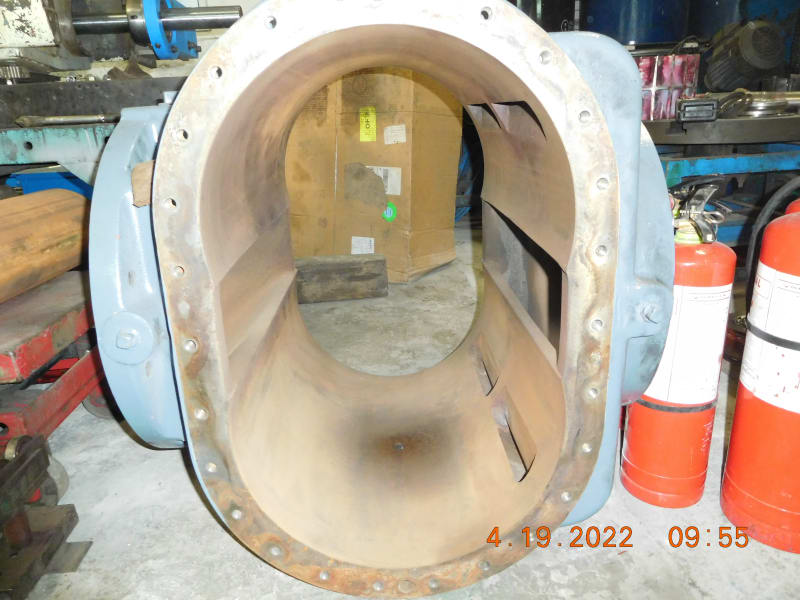
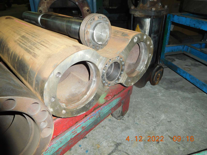
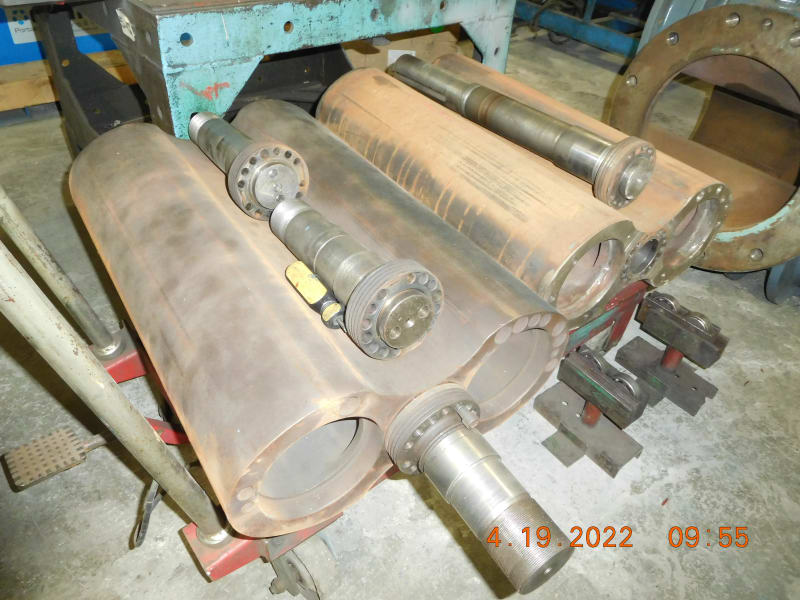
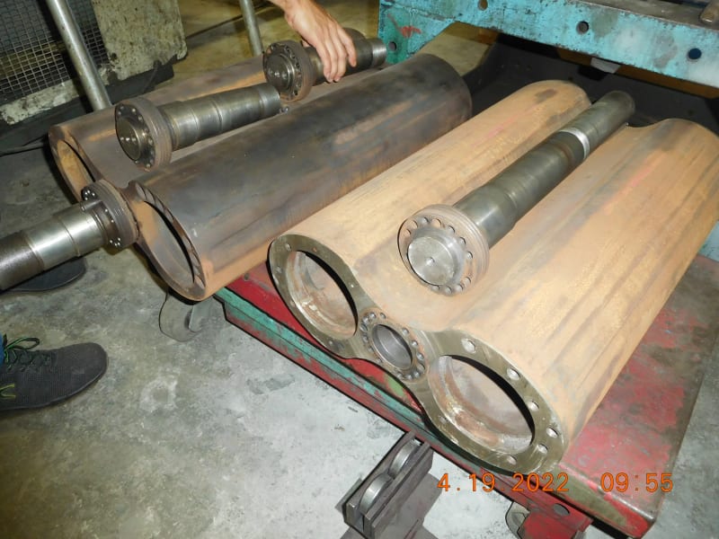
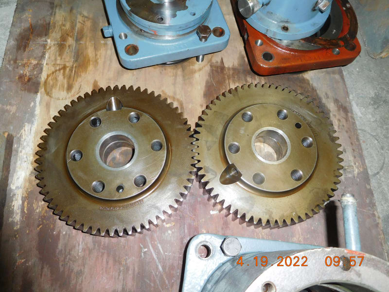
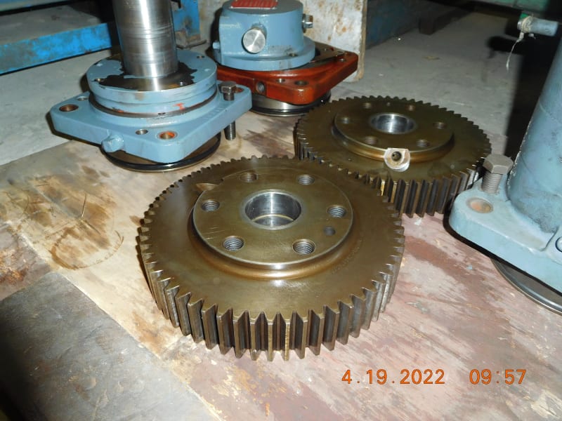
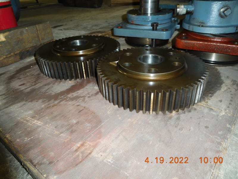
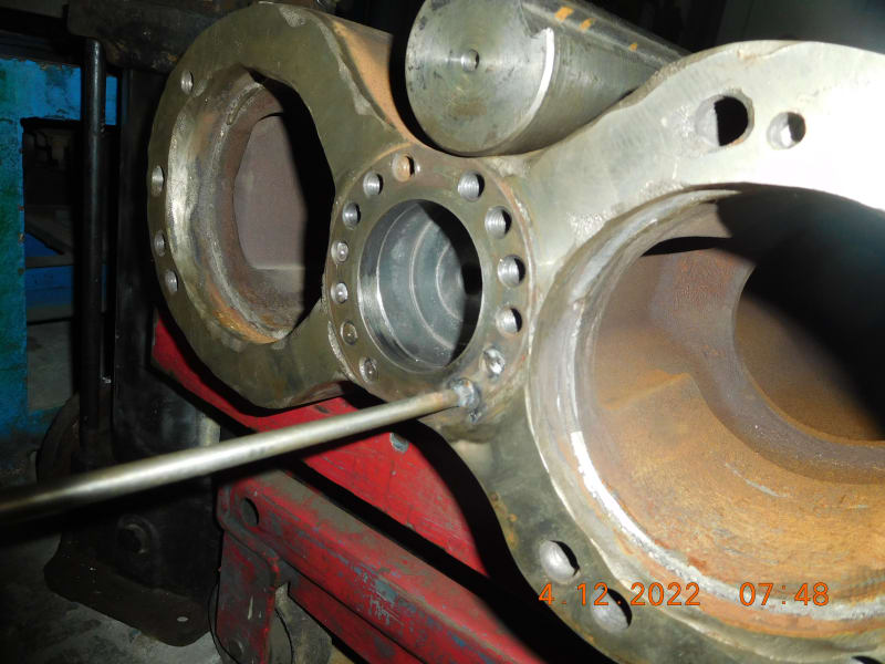
I have inspected well all the components and parts where everything is without wear on the surfaces of the cylinder, lobes, bearing fits, bearing journals, drive and driven gears etc., that should occur if a rubbing or sudden jerk of operation would prove. Please see the attached photo for your references and videos during operation on an open port.

Those marks you may notice on the head plate are just nominal to very slight wear. I suspect this mark happened after the breakage of the Allen cap screws as it took us time to withdraw the unit from the skid base of the blower.

And yes Tugboat I don't have any explanation on the corrosion of the allen cap screws yet as of now. I will try to check this and view it with your perspective as it might help us gather more information.

Thank you for patiently reading my feedback. I am just new on this website and there are a lot of photos and videos I wish to share and would still need time to study how to navigate this page.

Awaiting for any more comments and will surely be appreciated.

Have a nice day!

 
 https://files.engineering.com/getfile.aspx?folder=004e2ce3-5ec1-4f67-90cb-50e5e7556894&file=DSCN9453.JPG
Was the position of the rotor measured prior to disassembly? I have built a few smaller roots blowers for on engine applications. I have noticed two errors on all units I have disassembled.

For your case I would be very curious if the builder centered the rotor axially in the housing. The rotor should be set near the minimum clearance on the thrust bearing end and allowed to expand in the extra space at the axially free end. Centering the rotor could allow it to contact the housing opposite the thrust bearing at high operating temps.

The second issue I see is that the rotors get timed in the lead direction but not trailing. I have heard this cause some rattling during coasting as the rotors touch lightly.
 
Hi TugboatEng...

I wasn't able to measure the clearances prior to disassembly as I was directly worried if the drive shaft snapped like JJPellin said. But during the process we got a discovery of broken allen cap screws...

Yes we got the correct clearances prior to assembly before just like you mentioned but I am not sure of the timing of trailing and leading. Could you please enlighten me about this? From what I also remember is the timing were also synchronized well. I would appreciate your experience on this please.
 
 https://files.engineering.com/getfile.aspx?folder=ded9dbf2-2242-499e-9f9d-67d63b78c04b&file=DSCN9459.JPG
Here are some of the photos I have gathered more...
DSCN9453_nz6l8o.jpg
DSCN9454_umxprl.jpg
DSCN9425_qgdmpl.jpg
DSCN9457_qpu9zn.jpg
DSCN9455_xfcuip.jpg
DSCN9458_irqadb.jpg
DSCN9459_eq9fyq.jpg
DSCN9462_rudor2.jpg
DSCN9410_ielnrs.jpg
 
I realize now, I have only built blowers with helical rotors. They also have helical drive gears that need to be shimmed to advance or retard the rotors. My experience in this regard does not apply to your case.
 
By the way the lobes were already re-built via puddle torch (Spray and fused) and was fused perfectly. It may appear on an irregular shape and finish but clearances were acceptable...I tried to upload a video but couldn't send it due to errors showing on this site...

Thank you for any comments on this.
 
Hi again everyone...

Is it also possible that the back pressure due to blockade or restriction of flow can really snap all of the 14pcs Allen Cap Screws of the drive shaft and also ending up cracks on the body of the blower as well as gear head plate and drive head plate? I can't help but think of this problem due to my previous blower repair (a smaller model by 20% only) almost had an accident as operators forgot to open the valve for 1 to 2 minutes until one of the inspectors notice it and immediately shut down the machine then instructed the operators to open the valve. During this process we notice an immediate rise of temperature in the body of the blower. Could it be that this happened also to this bigger blower that we recently repaired?

Thank you everyone for your feedback.

 
Hi Johnny Pellin.

I notice also that the belt of the blower during operation has a higher tension than expected during my trial. I didn't mind it as I thought it was just normal. I think your theory is also one to consider. Operation would reason to me that it has been that way ever since and haven't any issue before so I would need a better and compelling reason to convince them of changing to cog belt.

Thanks again.
 
Cogged belt? Yeesh, straight rotor roots blowers are already loud enough.
 
Discharge pressure on roots blowers is limited by either the drive belts slipping (does not happen with coged belts) or the motor breakdown torque adjusted by the belt ratio. This puts the maximum pressure with a blocked discharge valve at 2.5x or more.
If your design does not have a relief valve it is easy to imagine you can exceed the casing structural load limit. you can calculate bolt shear stress applied from motor breakdown torque in a similar manner.
 
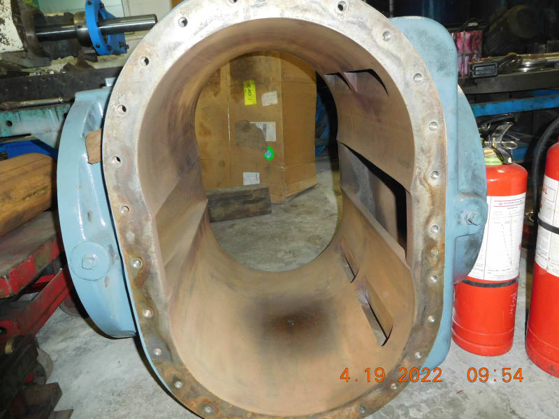
The photos show a lot of corrosion on the housing inside and rotors outside. If that was present during operation, couldn't that be the reason of the problems?
 
Status
Not open for further replies.

Part and Inventory Search

Sponsor