Continue to Site

Eng-Tips is the largest engineering community on the Internet

Intelligent Work Forums for Engineering Professionals

  • Congratulations KootK on being selected by the Eng-Tips community for having the most helpful posts in the forums last week. Way to Go!

Rotation ability for shear end plate connection 6

Status
Not open for further replies.

TTTKAO

Mining
Aug 24, 2022
78
Hello all,

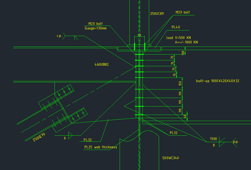
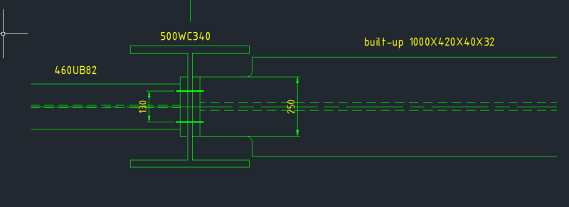
i am working on a girder beam(1000X420X40X32) to column web(25mm) connection with a big shear load(500KN) and transfer load(+/- 1000KN). i am using shear end plate (32mm) to transfer the load. a very thick endplate needed after considering prying action( M20 steel bolt is used). I have a little concern about the rotation ability for the girder beam as the end plate is too thick.it may become a semi-rigid connection which can take some moment which i don't expect to see. but from another side it seems impossible to use a thin end plate due to the heavy section and big design load. i am wondering who can give some suggestion and opinions for this detail? i attached the detail for detail information. and are there any good articles addressing end plate connection rotation ability?

thank you!
2_ru15vm.png
1_xd8wkc.png
 
Replies continue below

Recommended for you

Looks like a conventional connection, albeit for high loads. I've used similar connections often. I generally use the AISC method to determine minimum plate thickness to use for prying action. A little thicker plate is cheap when it comes to added bolts. In these environs, M19 bolts are less costly than M20. Do you need a CP weld? That connection will not act like a pinned joint.

-----*****-----
So strange to see the singularity approaching while the entire planet is rapidly turning into a hellscape. -John Coates

-Dik
 
isn't he "just" welding the endplates (and the corner gusset) onto the beams ?

"Hoffen wir mal, dass alles gut geht !"
General Paulus, Nov 1942, outside Stalingrad after the launch of Operation Uranus.
 
Hi Dik,

CP may be not required, the web thickness is only thin, there won't be a big difference between fillet weld and CP. "the connection will not act like a pinned joint" is really concern from me. i plan to add a knee brace under side of girder. in this way, i can release moment of girder end.


Thank you
 
A knee brace may not help, and may make things more difficult. Can you not connect to the column to develop the moment resistance? The column moment is about the weak axis and would be determined largely by the rotation of the 1000 built up girder, which shouldn't be a lot.

-----*****-----
So strange to see the singularity approaching while the entire planet is rapidly turning into a hellscape. -John Coates

-Dik
 
Is there a reason you can't use standard clips on the 1000mm side? Why the endplate?
 
Hi JLNJ,

there is a very big transfer load, the available angle thickness won't work due to prying action.
 
Hi Dik,

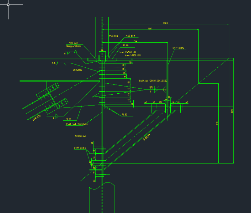
i am struggle with this, as the girder connect to web of column, it won't be a real moment connection. the full rigid moment here is around 2200KN*m as per analysis. I think the real moment will be much lower than this number, may be 50% of this number, but it's very hard to say. This's the reason i try to use knee brace(250UC79), after adding the knee brace we can assume it's a real pin connection at girder end(tension under gravity), the knee brace will be compression link under gravity load. the moment happened under normal operation load combination which makes me cautious to estimate the moment at the girder end. I attached my knee brace detail, seems not such bad. and May i ask if you have other suggestions regarding this joint connection?

Thank you so much for the help!

3_vrqbqp.png
 
Can you plate across the toes of the flanges and use a stiffener plate, too?

Can you use a bearing connection for the girder and avoid a moment connection completely? The use of clip angles (JLNJ suggestion) will greatly reduce the moment.

-----*****-----
So strange to see the singularity approaching while the entire planet is rapidly turning into a hellscape. -John Coates

-Dik
 
I don't see how you can possibly justify that as a pinned connection. It would absolutely behave in a semi-rigid manner. I'd first start asking the question whether semi-rigid is a problem here. If it absolutely is then I'd start chasing a better connection.
 
Your original connection is commonly accepted for this scenario. It has some ability to attract moment, but opposing end-plates are one of the best methods to transfer axial loads through column webs. We're obviously working with different codes, but you can make the original detail work just fine. Steel is fun because you can control the load path by sizing your welds/connecting-elements. That will draw the axial load in certain proportions to the desired elements.
 
you are right, that's one of my concern. this will be semi-rigid connection, but it's hard to estimate the how big moment it will be .if i assumed 50% of full moment value , check this connection as per flush end moment connection following AISC DG-16, it will be failed. i try to find a way to solve this problem, even it's a bit conservative.

Thank you
 

I consult with my team members as well, that's true, they used this kind of connection to transfer big transfer load before as well. but seldom to be used in such deep girder. that's why i am considering to add the knee brace underside. this is additional constrain, but i think make the connection safer....
 

I prefer to let it yield and then deal with it.... [tongue]

-----*****-----
So strange to see the singularity approaching while the entire planet is rapidly turning into a hellscape. -John Coates

-Dik
 
I wouldn't normally add a knee brace. It will attract too much moment, I suspect and you have the weak axis of the column... Deal with the connection and try to make it as flexible as you can (unless you need the moment resistance for other reasons).

-----*****-----
So strange to see the singularity approaching while the entire planet is rapidly turning into a hellscape. -John Coates

-Dik
 
Hi Dik,
Thank you so much for the suggestions. this connection has limitation due to the site conditions.

Can you plate across the toes of the flanges and use a stiffener plate, too?

sorry what does this mean?

Can you use a bearing connection for the girder and avoid a moment connection completely? The use of clip angles (JLNJ suggestion) will greatly reduce the moment.


it's had to use bearing type due to site condition and the steel structure. i can't find thick enough angle to resist prying action here.


Regards!

 
Hello All,

Thank you so much for the suggestions and questions, i appreciate it a lot. By adding the knee brace, the full moment value reduced to 50% of no knee braces by analysis. considering it will be a semi-moment joint, i think the girder beam connection will be strong enough.
may i ask, are there any technical concerns from you for the knee brace option except more complicated of installation. i am working in heavy industry, the important equipment is sitting on this girder. Client should be ok with erection...

Thank you!
 
ArcherC, i think that when dik said that the knee brace will attract too much moment, he's not talking about the moment exaclty at the Girder-Column connection but the moment created by the binary of tension on the connection and compression on the Knee brace. I also think that this moment will be much greater since the connection with knee brace is much stiffer. If this Moment is not a problem to your column then the connection with knee brace is IMO adequate.
 
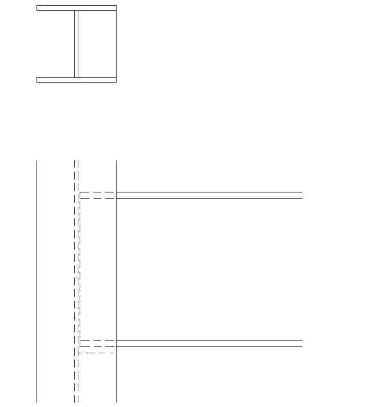
can you do something like...

Clipboard01_jd9uca.jpg


-----*****-----
So strange to see the singularity approaching while the entire planet is rapidly turning into a hellscape. -John Coates

-Dik
 
ArcherC said:
you are right, that's one of my concern. this will be semi-rigid connection, but it's hard to estimate the how big moment it will be .if i assumed 50% of full moment value , check this connection as per flush end moment connection following AISC DG-16, it will be failed. i try to find a way to solve this problem, even it's a bit conservative.
It seems like you are one the right track.

What fails? Is it an actual failure? Or just a code failure. You say AISC DG-16, design guides are normally just that. Guides. You as an engineer can decide to ignore 'failed' results.

If it is a brittle failure then it might be something to worry about, if it is a ductile failure mode or simply a design guide failure then it probably isn't an issue. Also if you dug deep you might find your 50% moment is way too high. You could consider a 50% of the moment capacity of the web and forget the flanges. Most likely the connection will be 'fine' but demonstrating that is the case can be the harder part.

I recently had a vaguely similar situation with short members and relatively high loads. I couldn't easily achieve a pinned connection without introducing excessive eccentricity and torsion on the primary beam. I ended up designing flush end plate (semi) rigid connection, any torsion on the primary beam was then compatibility torsion and thus limited.

I say semi-rigid because according to my relevant code and recommended design guides it didn't pass the recommended requirements for a fully rigid connection. But the connection was still more than strong enough for the full moment even though it was probably only 60% of the stiffness of a fully rigid connection.
 
Status
Not open for further replies.

Part and Inventory Search

Sponsor