Continue to Site

Eng-Tips is the largest engineering community on the Internet

Intelligent Work Forums for Engineering Professionals

  • Congratulations SSS148 on being selected by the Eng-Tips community for having the most helpful posts in the forums last week. Way to Go!

Round HSS Column k factor

Status
Not open for further replies.

bridgebuster

Active member
Jun 27, 1999
3,969
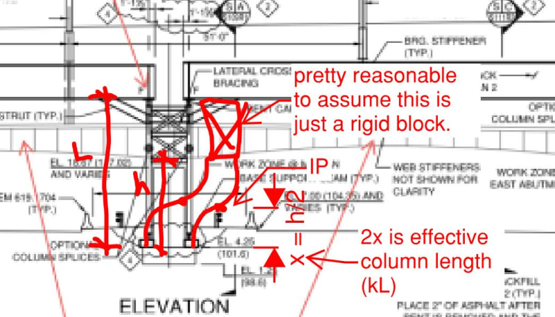
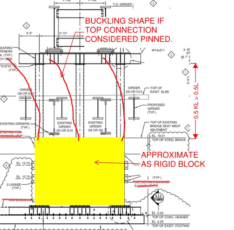
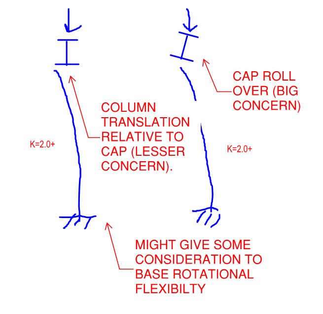
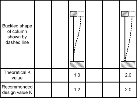
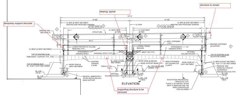
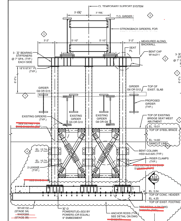
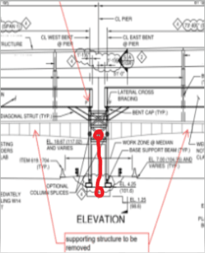
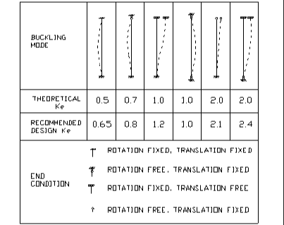
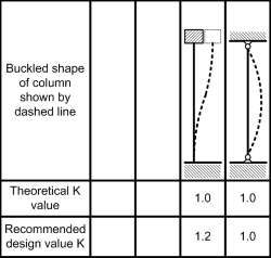
I'm looking at the design of a structure that will temporarily support a section of a viaduct while the structure it normally rests on is being replaced; illustration below. The pier columns are round HSS. The designer used a k factor of 0.8. In my mind k should be well north of 1.0. To me it's a frame with side sway in the direction of the bridge. The girders simply sit on the pier cap beam and are held with two bolts. I was wondering what others think. I have to post another illustration to provide further clarity.

a_hge5vs.png
 
Replies continue below

Recommended for you

The is the elevation of the temporary pier at the abutments. Granted, the columns are welded or "fixed" at the bottom grillage beam and the top cap beam. In the transverse direction I can buy k = 0.8 but to me in the longitudinal directions it's a pin at the bottom and no lateral resistance. The temporary center pier isn't giving me too much grief; it's the ends I'm worried about.

b_b5t9b8.png
 
Just to remind you that you can use the column alignment chart (from Structural Stability Research Council) to get more exact K value, based on the rigidity of the members that framing into it.
 
I did use the alignment chart. As I said, in the second illustration 0.8 isn't unreasonable, though I would prefer 1. It's the k factor in the longitudinal direction that I'm worried about. I don't think 0.8 is correct.
 
If I read correctly, your concern is stability in the direction of the traffic. It is tricky, if the displacement of the upper joint is small, you can assume pin-pin condition, then k = 1.0. If the upper joint is free to translate, the k = 2.4. Huge difference.

image_liaily.png


image_zfzclj.png
 
Can you do a rational buckling analysis (eigenvalue analysis), stop guessing k factors basically as you'll always be wrong.

This is why codes allow you to use buckling analyses to answer questions like this. AISC360 allows you to work out the critical buckling stesss via a buckling analysis and substitute it to work out a design stress. I wrote a bit of a primer on buckling analyses on my blog a while back if you're unsure on how to proceed if you've never got into it before. While it was specifically related to AU/NZ steel standards, the process is virtually identical for design to AISC.

Alternatively use of the direct analysis method (DAM) in AISC is another option probably. Again built for exactly this reason, to prove under some notional buckling loads that sufficient strength exists.

One thing to be aware of is the two frames at the ends if they are pin/pin type connections top and bottom, any vertical load applied to these is also reliant on your middle frame to resist via buckling. Basically it's the sum of all the column loads causing buckling in the centre frame. Look up the "sum of P concept" in buckling related literature. If you look at the centre frame by itself in isolation with on its own load and a guesstimate of the effective buckling length you're possibly going down the wrong path (which you'll only know if you were to actually do a buckling analysis anyway).

AISC YouTube channel had a good video on this concept about halfway through.
 
If you're calling it pin-pin, k=1.0 as it must be braced to be stable, a la Agent666. If it has any fixity at either end but also braced, k<1.0.

What length is being used with k=0.8 in the transverse direction? It looks like a sway frame above a braced lower segment, so two segments per post. (If doing it by hand.)
 
Thanks Steveh49, I'll read that article when I get some free time.

But for now (pre Yura education!) your buckling analysis is elastic for an eigenvalue analysis, it gives you the theoretical critical buckling load.

The code you are using applies the column buckling curve to your analysis result to account for initial imperfections, residual stresses, inelastic buckling, etc, exactly like you would if you guesstimated the K factor. Both AISC and AU/NZ codes do it this way. Basically it is identical to doing it by hand if you guessed the exact right K factor, except the analysis indirectly gives you the K factor if you wished to back calculate it out and no guessing is involved. See the example I did on my blog I linked to, to give you the idea. I showed for both normal hand way and buckling analysis way the same result is achieved with a simple example to AS/NZS steel codes. AISC allows you to also sub in the buckling stress worked out from the critical buckling load.
 
I would normally go with direct analysis for this one. k=1.0 is then given, and the appropriate length to use seems straightforward for all members. Direct analysis will automatically take care of the lean-on 'sum of P' issue on the median tower (ie for lateral design of the tower), whereas that needs to be done manually for design by buckling analysis. Correct me if I'm wrong. Direct analysis is less useful if the length for the buckling check isn't obvious.

But this a check of another's design which used k<1.0, so the buckling analysis would be needed to justify that IMO.

Bridgebuster, is there a reason that the median tower isn't braced down to ground? Access between the legs? I believe a stiffer tower would result in less lateral bracing force from the abutment columns.
 

Apparently the designer has provided X bracings at top levels above the pier. If you have concern, you may ask the connection of columns with horizontal strut elements at the top levels of both abutments to reduce the buckling height and for extra support to limit the sway in the direction of the bridge.
 
All, Thanks for your thoughts.I'm not the one who has to redesign things. I was look at a proposed design change of a connection. While looking at the calculations the allowable column stress didn't make sense. So I went to the complete set of calculations and saw they used k= 0.8 in the longitudinal direction when there isn't true frame action, it was OMG! I notified the powers that be FWIW; at least there's a still a small window of opportunity to straighten things out.

@retired13 - yes, I'm worried about stability in the longitudinal direction; I agree k needs to be higher. The unbraced length at the abutment columns is also low.

@steveh49 - there is a solid pier in the median, the X bracing can't be brought all the way down.
 
bb,

Thanks for the response. I agree that 0.8 wouldn't fly/hold in this case. Good luck.
 
bridgebuster - Have though about this problem for two days. For several reasons, I estimate the "K" value for the design shown could be based on a blend of these two conditions:

Column-Assumed-250_uyfmpw.png


I propose K = 1.1

[idea]
 
Speaking only to the direction parallel with the via duct.

1) I'm okay with k = 0.8 for the end columns assuming that they are fixed based and gravity only columns with the center bent serving as the lateral system.

2) If the center bent is the lateral system and has fixed-ish bases, I'm okay with 0.8 there as well based on the sketch below.

3) Agent666's point about the middle bent needing to stabilize all of the gravity load of the system is spot on.

c02_yep6jb.jpg
 
Hopefully the connections between the tops of the columns and and the beams at the tops of the bents possess some rigidity. If they were pinned, I suspect that you'd have [k > 1.0] in the transverse direction as well.

C01_cskloi.jpg
 
SRE - Friday, I did some rough calculations using the AISC alignment charts and came up with 1.6 and yesterday one of coworkers proposed 1.3; it's mores or less in the middle of 1.1 and 1.6. Meanwhile, his D/C ratio with 1.3 is much better than what was originally calculated with 0.8; pulling my hair out.

KootK - I can live with 0.8 at the center tower and 0.8 in the transverse direction at all three piers. However, longitudinally at the abutments I can't rationalize 0.8 because the girders on the pier cap are essentially just sitting there. They're connected to the cap beam with two bolts in slotted holes.

 
bridgebuster said:
However, longitudinally at the abutments I can't rationalize 0.8 because the girders on the pier cap are essentially just sitting there. They're connected to the cap beam with two bolts in slotted holes.

Whoa... if you don't trust the pier cap to brace the tops of the columns translationally, that makes things simple:

1) K = 2.0+ (cantilever) baring some ridiculously complex analysis to incorporate whatever connection lateral / rotational stiffness is available at the top.

2) The practical solution is surely to change whatever needs to be changed such that you are confident that you have transnational restrainer at the top.

If the issue is only about potential translation through the slots, I'd be less inclined to sweat that as the cantilever mode buckling will be self limiting.

C01_qh5zz1.jpg
 
The lean of the columns will only be slight before the bolts engage in the slots.

Does the lateral stiffness of the median tower qualify it as a column brace per the code requirements? If not, bite the bullet and analyse by computer. You've already got three K values from 0.8 to 1.6, including a fundamental disagreement on whether the column is braced or sway. Agent666 foreshadowed this.
 
bridgebuster said:
...it's mores or less in the middle of 1.1 and 1.6

Taking another look at this today, I now see a lower bound of 1.2 and an upper bound an upper bound of 2.0. But, closer to the lower bound, just as you (1.6) and your coworker (1.3) have figured:

ColumnEffectiveLength-450_yqrqzz.png


[idea]
 
Status
Not open for further replies.

Part and Inventory Search

Sponsor