Continue to Site

Eng-Tips is the largest engineering community on the Internet

Intelligent Work Forums for Engineering Professionals

  • Congratulations SSS148 on being selected by the Eng-Tips community for having the most helpful posts in the forums last week. Way to Go!

Round HSS Column k factor

Status
Not open for further replies.

bridgebuster

Active member
Jun 27, 1999
3,969
I'm looking at the design of a structure that will temporarily support a section of a viaduct while the structure it normally rests on is being replaced; illustration below. The pier columns are round HSS. The designer used a k factor of 0.8. In my mind k should be well north of 1.0. To me it's a frame with side sway in the direction of the bridge. The girders simply sit on the pier cap beam and are held with two bolts. I was wondering what others think. I have to post another illustration to provide further clarity.
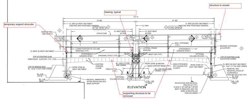
a_hge5vs.png
 
Replies continue below

Recommended for you

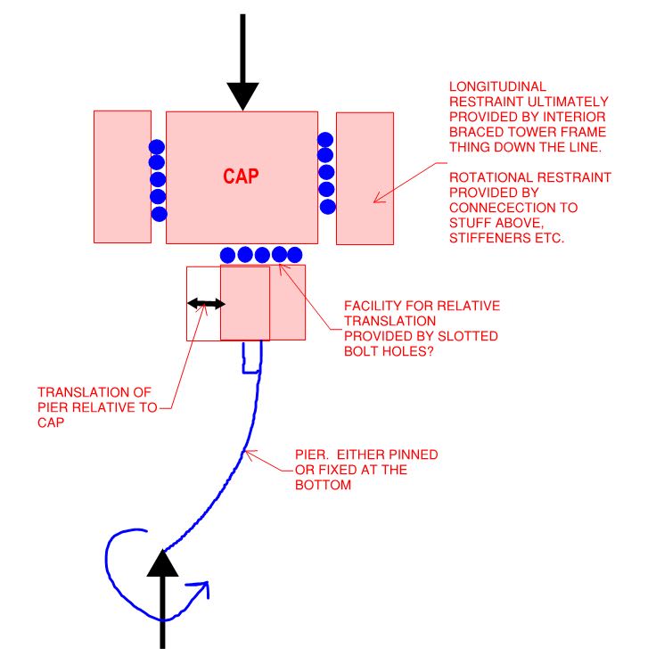
@SRE/Bridgebuster: I've been struggling to wrap my head around the stability model that you guys must be using to come up with the values that you have been. Is it the model shown below? If so, then I suspect that a K<1.0 could be justified based on:

1) The self limiting nature of the translation made possible by the slotted bolt holes and;

2) The high probability that there's enough friction between the bottom of the cap and the top of the pier to effectively prevent any translation and successfully brace the tops of the piers laterally.

This probably isn't how I'd design such a thing from scratch myself but, given the model below, I feel that it could be justified at the upper end of the acceptable, liberal design spectrum.

C01_z8kl5a.jpg
 
Again, thaks for your opinions. Internally, we have no agreement. Some are proposing K=2.1, in which case the columns are DOA. To me there is translation but as steveh49 notes it's limited to the length of the slot; what I'm wrestling with is the degree of rotation at the top. The girders are on bearings. Will the rotation of the girder rotate the W14 cap beam? To me there would be some rotation. The columns aren't acting like true flag poles. If k =1.2 my problems go away; 1.3 slight overstress; 1.6 DOA.

I'm toying with flipping the bearings and the diagonal brace but the design has to be rechecked and even if it work, it's a lot of rework for the fabricator.


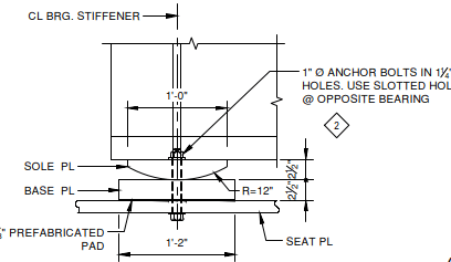
today_rypkfg.png
 
Are the slotted holes that you've been mentioning, the slotted holes in the sketch that you just posted? So they exist between the girder and the cap rather than between the cap and the pier?
 
bb said:
The girders are on bearings. Will the rotation of the girder rotate the W14 cap beam?

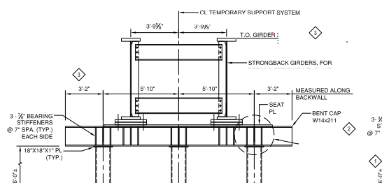
The quick answer is no. As the girder is on roller support, the cap beam is free from rotation of the girder, if the bearing pad functions properly. But the cap beam will translate in its longitudinal axis due to the oversized hole and the slot hole at the opposite end.

image_h55hcl.png
 
I view the problem from the bridge construction angle. This temporary structure is being retrofit onto an existing bridge. Despite the best planning, there will be deviations from intended alignment. Assuming "ideal" fixed bottom connection and pinned top connection (K=0.8) is totally unrealistic for "as-built" conditions.

Additionally, it's apparent that column loads are really high (Note the 2-span continuous W14x211 cap, with stiffeners everywhere). I'm not convinced the bottom connection is fixed, although it's more fixed than pinned. For example, IMHO, the riser clamps "look" good, but are of limited value under high load.

Also, bridgebuster has persuaded me that the heavily loaded beams at the top connection are translation free. With heavy loads, the bolts are not going to stop movement, especially if there is unavoidable variation from planned alignment.

Selecting a more realistic value for K is a good way to address the ill-defined conditions.

[idea]
 
Are there good reasons for this being the way it is?

- Do you need expansion piers? Those columns look pretty slender in the elevation and the structure may be shaded (?), so maybe the stresses are manageable without slotted holes.

- What happens if the expansion connection binds up due to friction, despite slotted holes? (ie as above).

- If the lateral stiffness is sufficient, and the stresses above aren't manageable, is pin-pin for the abutment piers feasible?

- Can you brace off the existing abutments and pier?

Large k factors should be used with care IMO, as they are a way of accounting for under-estimation of stresses when designing the member. The stresses on the connections need separate consideration.
 
An update, the consensus is that k should be around 1.2. We have an independent engineer who is going to model things and give an assessment.
 
Not sure if this has been considered, but thinking about the arrangement again, one thing I see as a concern with using a sway structure for propping is that as it is loaded towards it's buckling limit it wants to move laterally. This goes against the desire that you typically want whatever you are propping to remain in alignment for the most part.

At least if you use something like the Direct analysis method you'll potentially get a feel for how much it might move under a set of notional loads that correspond to the design loading to either address or discount as the case may be.

There are obviously constraints at play here, but my go to would be to always try brace temporary propping wherever possible.
 
Status
Not open for further replies.

Part and Inventory Search

Sponsor