Continue to Site

Eng-Tips is the largest engineering community on the Internet

Intelligent Work Forums for Engineering Professionals

  • Congratulations KootK on being selected by the Eng-Tips community for having the most helpful posts in the forums last week. Way to Go!

Rule of thumb: Numbers of Doublers i 6

Status
Not open for further replies.

SteveAero

Aerospace
Apr 28, 2019
17
Hi,

Is there a general "rule of thumb" that addresses the amount of doubler repairs that are allowed on a fuselage skin, specifically for FAR23 a/c? Something like a density requirement. I know that some OEMs (FAR25) mandate a full stringer frame bay surrounding a 'significant' dent must be damage free. I wonder if the same would apply for doublers...?
 
Replies continue below

Recommended for you

so you're repairing a dented dblr ? (or repairing a dented skin with a dblr ??)

I would be concerned about repairing a dented dblr as that'd mean a pretty significant impact (to dent possibly 0.08" to 0.10" of skin ?
And it'd mean a pretty significant repair dblr after cutting out the dent.

But you talk of repair density ? so you've got multiple dents thru a dblr (and skin) in a single bay ?

Why not one large repair dblr to cover all ?

another day in paradise, or is paradise one day closer ?
 
I don't think there is any rule of thumb, I assuming you are considering a pressured fuselage?
There is bigger variations of fuselage construction styles with FAR23 commuter cat than FAR25? Flat sided fuses, round fuses, single row fasteners, steel doublers, bonded structure, etc, etc

Can you give any more detail
How much airframe life is left?

I would say so long as the stress fields relating to the repairs don't interact, including out of plane bending due to the doubler stackup would be my first pass answer. But it would depend on the detail design of the repairs do they have modest margins or very large margins.

 
I would NOT treat proximity of reinforcing repairs in the same way as proximity of damage to dents. There are so many variables at play it is impossible to give a detailed response. In general, aircraft SRMs sometimes have a limit on the repaired surface area before an additional evaluation of the aerodynamic impact is required.

But there are MANY other things to consider:
- Location on the airframe - is is aerodynamically critical or no?
- Protruding or flush fasteners?
- Mix of doubler / tripler repairs with single doubler repairs?
- What is the overall proximity? Are we talking a few inches between some? What are the size differences?
- How are the repairs arranged - longitudinally aligned, circumstantially aligned, in diagonal bays?
- Do any of the repairs cross over production splices?
- Are any of the repairs being put on top of previously repaired locations - how many times have production holes been enlarged?

Generally the altered stress fields in the skin around the doublers might not interact unless there is separation on the order of a few inches. However, the stiffness changes, particularly if multiple doublers cross into a single bay, can cause the load in the skin to distribute in odd ways. You could also have MSD concerns is you are putting a lot of holes in a row in a highly repaired airframe, especially near production splices.

This is why I always insist on seeing pictures on the scale of skin bays when I am providing repair instructions, and have notes in any repair plan regarding other repairs in proximity.

In general, I would say: if you are using an SRM repair, follow all SRM limitations. If an engineer is providing repair instructions, inform them of any repairs on the subject skin panel or any adjacent skin panel, and let them perform an assessment of the impact.


Keep em' Flying
//Fight Corrosion!
 
Thanks for all the useful feedback.

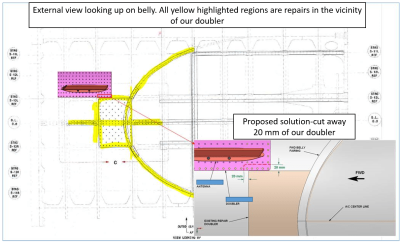
Valid points made about the altered stress field in the skin due to the many repairs. I attach a sketch of the problem and would love to know everyone's advice and thoughts further.

To clarify things, I'm working on adding a small antenna to the belly of the fuselage. We are not the OEM, so I am basing all analysis on conservative assumptions. The doubler is there to carry the antenna loads to the adjacent stringers/frames, and to reinforce the 1" skin hole for the system cable. Due to large-scale corrosion on the a/c (7500 Flight Hours and 5000 cycles), the OEM performed massive repairs on the skins/frames and stringers. This leaves us not too much room to attach our antenna. The sketch shows a suggestion to cut away 20 mm of our doubler, but is that enough?
 
 https://files.engineering.com/getfile.aspx?folder=188e77cc-af31-46cf-a778-6235aec11804&file=Query_for_Eng_Tips.PNG
Is this pressurized structure? Is this an STC?

Regarding your statement: "The doubler is there to carry the antenna loads to the adjacent stringers/frames"... I would not rely on the doubler as the load path for antenna loads to the substructure. If there are significant antenna loads you should have intercostals etc. Looks like a small antenna, so I'm not sure exactly what you need. But I would only consider the doubler as reinforcing the cutout.

Now, those doublers are encroaching on one another. If this were my decision I'd say remove the existing repair and incorporate the previously repaired area into one doubler including the antenna area. Extend the periphery of the doubler at least one row beyond the existing repair holes.

You will need to analyze the effects of the new doubler configuration on the underlying stringer repair (which has fasteners c/t the skin reinforcements).

Now most importantly...who is approving this and have you been talking to them?

Keep em' Flying
//Fight Corrosion!
 
Whats the inspection regime for the existing repair, is it acceptable if that ends up being applied to your doubler?

Is the existing repair doubler thickness = > full skin thickness, the repairs fastener detail isn't what would be considered industry practice. If that is the case that would mean you can review your fastener number and pitch assumptions.

Guess you have check the intended antenna location for any small skin blendouts?

Possibly you could split your doubler into an inner and outer to get more flexibility in the layout.
 
Thanks LiftDivergence,
This is a pressurised structure, and an STC. It's a low aspect ratio antenna, so the skin/doubler combo panel can handle the out-of-plane bending loads, even superimposed with global loads. Is replacing the doublers with one large doubler the only viable option?
verymadmac, the skin and doubler are 0.032" and 0.05" respectively. Not sure what an inner doubler would solve...
 
why are you adding a dblr ? a low profile antenna shouldn't introduce big loads into the structure. even if you have a large (like 3" dia) hole and you don't (having read your posts again !?). you may find a better solution is to live with the Kt and to have a simple (visual) inspection of the hole; as opposed to a much more complicated NDI inspection of the dblr.

A part23 a/c will probably have a very low hoop stress, something like 6psi*36"/0.04" = 5.4ksi; so this says that the resulting inspection with Kt = 3 should be ok.

another day in paradise, or is paradise one day closer ?
 
I'm not saying it is the only viable option, but it is the one I would want to move forward with if it were me. Since this is an STC, I am assuming the STC Holder / ODA / a DER is involved in the approval process. I would ensure they are on board with everything.

There is a study of skin stress effects due to doubler proximity in AFRL-VA-WP-TR-2000-3030, Appendix E. However, these doublers are not just in proximity, they are butted up against one another. Even if the stresses are low, there are eccentric bending stresses in the skin primarily near the doubler outer rows. Having the doubler edges like that will create complex stress details in the skin which will be hard to predict. It is a poor stress riser detail and also poor from a damage tolerance standpoint. I'm not sure why they would not be encompassed together if given the opportunity

Also, since it is an STC, you need to re-evaluate the static substantiation and DTA for the STC in general, since this aircraft no doubt deviates from the intended STC drawing installation. So it's not as if your analysis will be any more complex. If you combine them it should be simpler actually.

Are you treating this as a repair or as a modification to the STC? That is, will this configuration be included in the MDL etc, or is it being given a repair approval? It sounds to me like this was found during installation of the STC. If that is the case, it should be considered a modification, which means DTE (if required) needs to be completed before flying.

Keep em' Flying
//Fight Corrosion!
 
Hi Steve,
I'm mostly supportive of the comments you've received from LiftDivergence. I've done a number of antennas just like this one, and he's covering a lot of it.

Two ways this could go:
You "should" be willing to combine these doublers because it is structurally more efficient and easier to substantiate,
OR
You "should not" be willing to remove the existing repair because it's subject to SID's or something else that would be awful if you touched it.
Do your research.

Some other important outstanding questions (you're under no obligation to tell us everything but I often wonder why people are so reluctant)
- What is the exact certification basis of the aircraft?
- Will you be providing your substantiation to a DER (or other equivalent)?
- Have you run your questions by them?

You always want to get your approving authority on board with your plan BEFORE you carry out the plan. If they've done an antenna patch before (and why would you be going to them if they hadn't done this kind of approval before?) then they must know what they're looking for. If they aren't happy to tell you, or you're afraid to tell them too much, well, I can give you MY phone number and we can do business.

 
There is no way in **** I would allow two doublers to be butted up against each other like that on a pressurized shell. Nor even remotely close together.
 
That's something either like a KU band antenna or a marker beacon (who installs those any more?) or maybe something for wi-fi.
Not particularly tall but has some serious surface area.

Doublers should be symmetrical. Not much point in having more rivets on one side than another, unless there are underlying structures that have to be matched. Doubler spans 3 bays, but there's probably only 1 (maximum 2) connector holes and a few screws in just 1 bay. It does not appear to me that you know what purpose your doubler serves.

Why can't this antenna be mounted 6 inches further to the left? (up in the diagram)

What's the reason for attaching the file so that everybody has to download the damn thing rather than just inserting it in-line? I almost missed it.
Like this:

Query_for_Eng_Tips_ahtsom.png


Sorry for the long delay. Thanks for all the great advice. LiftDivergence, thanks for the great reference. SparWeb, sorry for the embedded file-I'll know for next time...
 
I also missed the attmt. I think the proposal worse than butting the dblrs, not that I like butting dblrs. My preferred approach (given that I cannot make the two dblrs into 1) would be to butt the dblrs and add an external splice, 4 rows of rivets (2 on each dblr). The next important detail is where are the stringer rivets ? If along the original dblr, then I'd pick these up with the new dblr. (There are two schools for this, to either terminate the dblr on the stringer rivets or off them; these two schools are as divided as Catholics or other religious denomination and Atheists !)

another day in paradise, or is paradise one day closer ?
 
Hehe rb1957. On that note, I understand why the last row ending off the stringer is better for inspection, but why oh why is it better for anything else, The area of the doubler compared to the skin is larger off the stringer and therefore it draws more load... am I missing something here.
 
ending off the stringer does give the opportunity for internal inspection of the fuselage skin, but getting there can be horrendous so maybe not such a benefit. Analytically the nicety is that the rivets at the edge of the dblr have a job to do (transferring load into the dblr) and those on the stringer already have a "daytime job" (transferring fuselage bending/shear loads); so why give these rivets two jobs ? The negative with this approach is secondary bending, introduced by the load transfer into the dblr being supported only by the thin skin (this is either Huge or "no problem" depending on your viewpoint).

ending on the stringer opposes all of these issues … the rivets are doing double duty (but the rivet's "daytime job" and this second duty aren't taxing to the rivet), the pressure skin is sandwiched between the external dblr and the stringer flange (so you have to do an NDI inspection, not that big of a problem on Part 25 planes), but the stringer is supporting the dblr edge effectively eliminating the secondary bending issue. Another issue with ending on the stringer rivets is that the fuselage CSK rivets will need CSK fillers (which they do in either case) but now these fillers are also subjected to the load transfer forces.

I learnt one way, others learnt the other … NP to me (until they say "you're Wrong").

another day in paradise, or is paradise one day closer ?
 
Great point about the stringer's 'day time job'. Also, while I have your ear, what is your opinion on the secondary bending moment transferred by a CSK fastener? Statically, this moment is high, but is it realistic? Also, what is your opinion on tab-outs/ fingers/fish mouths at the first row. That's also quite controversial...
 
How much moment can a CSK react ? IMHO, not much; does it matter ? no.

fingers along the edge of dblrs … at the risk of taking a great name in (some) vain, I think this is where Tom Swift went off the rails. Sure there's an academic benefit, being able to visually detect a crack (between the fingers); sure there's an academic benefit of softening the edge of the dblr to improve load transfer. Bu tI think these benefits are very small and very limited to places where you're already so "skrewed" that you need everything and anything to get near enough to a passing grade (you're in such a high cost environment that you can afford to spend your way out of the problem, or you're in such a high stress environment that nothing else works for you).

I've actually had to try something similar … cutting "inspection" holes into a flange between fasteners to see the crack growing in the substrate under the flange (ilo doing Xray inspections). My recollection is that we ended up using X-rays, about once in the life of the plane.

another day in paradise, or is paradise one day closer ?
 
Interesting 'take' on Swift. I hear your points.
Another opinion: there are differing sources for secondary bending; I'm thinking of Safarian, Schijve (neutral line) etc. Which one do you advise using?
 
Status
Not open for further replies.

Part and Inventory Search

Sponsor