Continue to Site

Eng-Tips is the largest engineering community on the Internet

Intelligent Work Forums for Engineering Professionals

  • Congratulations waross on being selected by the Eng-Tips community for having the most helpful posts in the forums last week. Way to Go!

Runout Tolerance Applied on an Assembly 1

greenimi

Mechanical
Nov 30, 2011
2,298
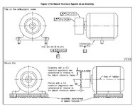
Why runout is used in this figure? (instead of profile)

What would be the difference between using profile (maybe even with dynamic profile modifier) instead of currently shown total runout?
Are there any mathematical difference between shown total runout and profile (again with dynamic profile maybe) ?


QTETIPS - Copy.jpg
 
Replies continue below

Recommended for you

Runout/total runout is not location sensitive. Profile of surface is.
 
Runout/total runout is not location sensitive. Profile of surface is.
Yes, I agree, but as shown, A primary and B secondary arrest all degrees of freedom, hence location of the tolerance zone (for the total runout) is fixed. Then I would say runout / total runout as being a location insensitive callout is largely irrelevant in this case. Am I missing someting? If yes, what?
(so what's the point of having a NOT location sensitive callout --here runout-- combined with the fact of stopping all the DOF's for the tolerance zone)

Getting confused now.
 
The location is not fixed. The axis can move anywhere up or down or right or left relative to the datum features and not change the runout. That is why there aren't any locating dimensions between the datum features and the surface that is being controlled.
 
Runout controls how smoothly the pully runs. Profile controls position accuracy of the pulley. Generally, the runouts are significantly smaller than profiles for this pulley or motor.

Best regards,

Alex
 
The location is not fixed. The axis can move anywhere up or down or right or left relative to the datum features and not change the runout. That is why there aren't any locating dimensions between the datum features and the surface that is being controlled.

So how profile with dynamic modifier will be different than the runout?
This tolerance zone (of the profile with dynamic modifier) may expand or contract while maintaining the form and orientation of the feature within the 0.3 tolerance zone, allowing the size of the feature to uniformly progress. Are both schemes mathematical identical?
 
The dynamic profile is relative to an ideal profile that is fixed or is a refinement within the limits of a profile that is fixed in location.
 
Dynamic profile releases the feature from size control, but not from location control. For example, If you apply the dynamic profile to the axial total ronout defined for the end face, then the tolerance zone (two parallel planes) would still be constrained in location to datum B (or to be more precise, orientation to datum A, plus orientation and location relative to datum B).
 
greenimi, if you insist, you could replace those total runout controls by dynamic profiles with customized datum reference frames that have only the rotational degrees of freedom listed :p
 
Burunduk and 3DDave,

I understand (I think) what you are saying, but if you take a look at figure 12-6/ 2018 states that total runout - case b.) and case d.) - clearly states that "LOCATION of the ENTIRE SURFACE" is controlled.
I know you can argue that only the AXIAL location is controlled and not the RADIAL location....
So when I am trying to understand the "new" definition for the runout (changed in 2018 FROM a dial indicator/inspection method based concept TO a tolerance zone based concept) everything falls apart.
Heck with the location and its runout limitations (or lack thereof)....I am already lost in the weeds.
I understand that the intent was to NOT change the runout tolerance, but that is NOt what they were doing...IMHO
Runout/total runout is not location sensitive


"
In past editions, runout tolerances were explained in terms of a measurement method using a dial indicator. See Figure A-1. For consistency in the explanation method used for other tolerances, the explanation of runout is now based on the resulting tolerance zone. The definition of runout tolerances was not changed."
 
I should have guessed that you would not put forth an argument in one go, but drop fragments.

Good job.

Enjoy the weeds.
 
greenimi,
You have to keep "LOCATION of the ENTIRE SURFACE" in its context. Which is relevant to 12-6: It centers the surface to the datum axis. In 12-16, the result also depends on how centered the cylinder is to the rotation axis (not a datum in this case), but it doesn't depend on the location error to the A,B DRF. Had it been profile (even dynamic), it would - hence the difference.
 
Runout if you spin the wheel.

Best regards,

Alex
 
Runout if you spin the wheel.
Per 2018 even is you don't spin the wheel (around the datum axis shown in the FCF) you can call it with runout?
At least, in my original picture 12-16, the wheel/ rotor is not spinned around any of the datums A or B (depicted in the feature control frame), but it is spinned around itself .....more of less like cylindricity.
Can we replace 12-16 with cylindricity (just the top total runout callot/ applied to the cylindrical feature, not the side / face/ planar surface)?
So we have dynamic profile (with customized datum reference frames that have only the rotational degrees of freedom listed) and runout still on the available options, right?

I guess, my point is: you don't NEED a datum axis which is part of the FCF in order to LEGALLY use runout (per 2018), which was not the case per the previous revisions of Y14.5 (1994, 2009), BUt in the same time THEY claim that "The definition of runout tolerances was not changed"......

Am I missing something here?
 
I guess the answer to the OP's question is: "Why not?"

There are hundreds of situations when it makes sense to measure runout of assembled part. And it it is done in thousands of shops tens of thousands of times.

And it's called "Runout". 2018 simply legalizes the fact.

Or take a look from the other side - imagine than on Fig 12-16 the pulley is placed in the chuck of a lathe instead of being assembled with the motor - is there a difference?

Important part is that even if tolerance zones are fixed, the part in question isn't. Tolerance must be satisfied in every possible position of a pulley (if you don't like the word "spinning")
 
Write the committee. They are back to implied datums again.
 
Runout FCF need a datum of axis. If you don't have an axis, then you don't have a runout.

Best regards,

Alex
 
Ooh, noo! The standard violates that requirement! The shock the horror. Time to repeal the 2018 version.

Honestly, the 2018 version did not make the world a better place.
 

Part and Inventory Search

Sponsor