Continue to Site

Eng-Tips is the largest engineering community on the Internet

Intelligent Work Forums for Engineering Professionals

  • Congratulations MintJulep on being selected by the Eng-Tips community for having the most helpful posts in the forums last week. Way to Go!

SAE 1144 shaft fracture surface morphology 9

Status
Not open for further replies.

GonzaloMartinez

Mechanical
Apr 9, 2015
24
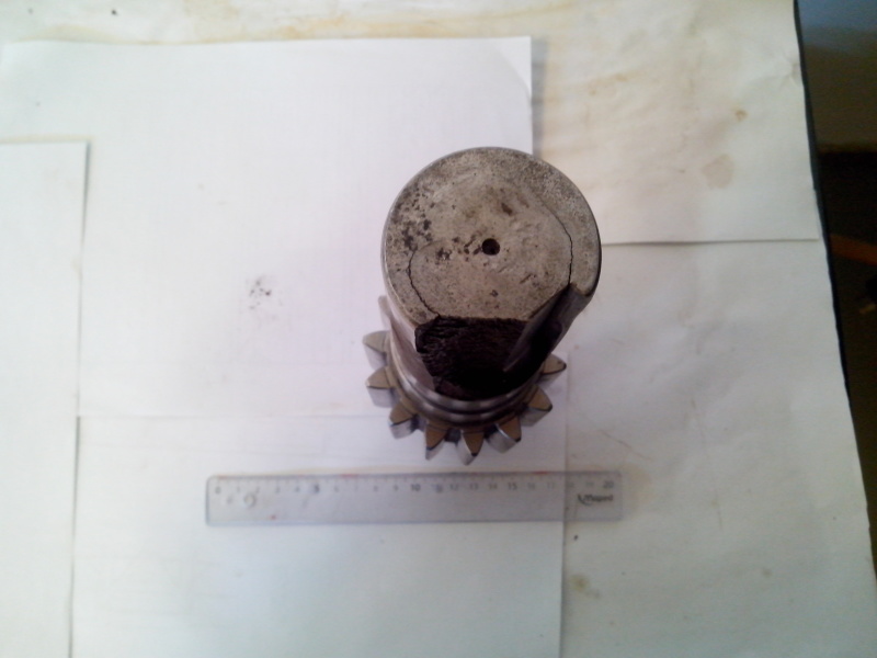
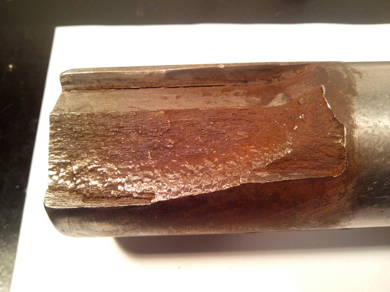
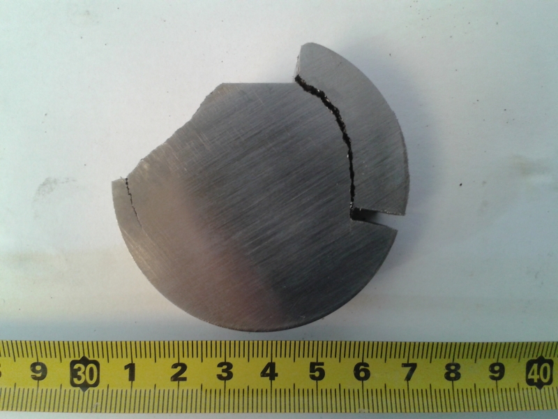
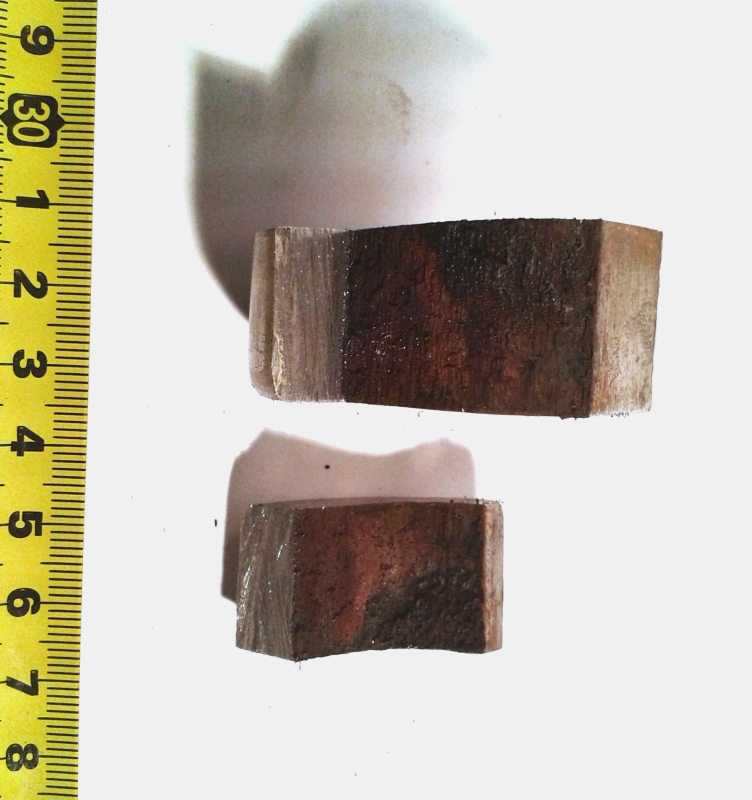
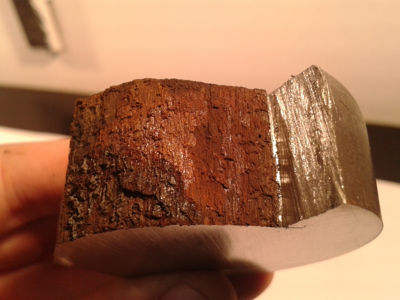
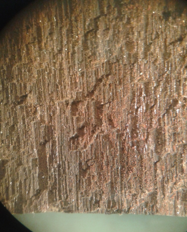
Hello everyone, I'm looking for some information about the type of failure and fracture surface appearance on this particular case: an sprocket shaft made of SAE 1144 (resulfurized steel) fails at de keyway showing long circunferential cracks in a way that makes me think that corresponds to a fatigue process. The thing that keeps me thinking is the faceted fracture surface that I´ve never seen in the cases of fatigue with which we have dealt before. Notice the sings of corrosion. Does anyone have any experience on some similar case? Thanks!


IMG_20150526_115213_gusy4s.jpg

IMG_20150526_115226_k2vi02.jpg

IMG_20150616_120820_g9kzrs.jpg
20150715_122155_an93pf.jpg
20150715_122249_lxuoyc.jpg
20150715_122436_c75yib.jpg
20150716_100926_eramnv.jpg
 
Replies continue below

Recommended for you

The circumferential crack propagating from the keyway is a classic fatigue mode for a shaft.
 
And the "woody" fracture surface appearance is typical of steels with elongated manganese sulfide inclusions, which grade 1144 has in abundance.
 
I would guess that a micro would show extensive banding and stringers, perhaps even in the same pattern as your cracks.
In general 'free machining' steels have very poor fatigue properties.

= = = = = = = = = = = = = = = = = = = =
P.E. Metallurgy, Plymouth Tube
 
Thanks everyone for your answers, they were really helpful. EdStainless we are preparing transversal and longitudinal metallographic samples, I will post some micrographs next week. I think that probably the best thing should be to select another steel grade for this use since machinability is not the determining factor.
 
Do you know if the shaft is supposed to be heat treated (hardened)? Was it? 1144 in the as-drawn condition with a large stress intensity due to the keyway will not have good fatigue resistance.
 
We did a number of hardness measurements from the core to the surface resulting in aproximately 29 HRC for every point, so I deduce it must be quenched and tempered but we will know for sure after the metallography.
 
From the (very nice) photos provided, the failure appears to consist of a pair of fractures that propagated from the key slot fillet surfaces. Based on the presence of a fair amount of surface corrosion, combined with significant deformation of the key slot flanks, I don't think your problem is fatigue per se. Instead, your root issues seem to be a lack of adequate corrosion protection and an unsatisfactory fit between the sprocket/key/shaft.

This component seems to be part of a gear drive. If the system was properly designed, including the shaft connection, I would expected a fatigue failure to occur first at the gear tooth root fillets which tend to have high tensile stress levels. Since the bearing journals and gear teeth seem to be in good shape, I don't think you need to change material. 1144 has advantages in terms of inherent mechanical strength, low cost, and machinability, so I'm assuming that's why you chose to use it in the first place. What you need to do is apply an appropriate type of corrosion protection to the exterior shaft surfaces, and redesign your sprocket/shaft connection so that it is rigid and there is no possibility of relative movement at the contact interface.
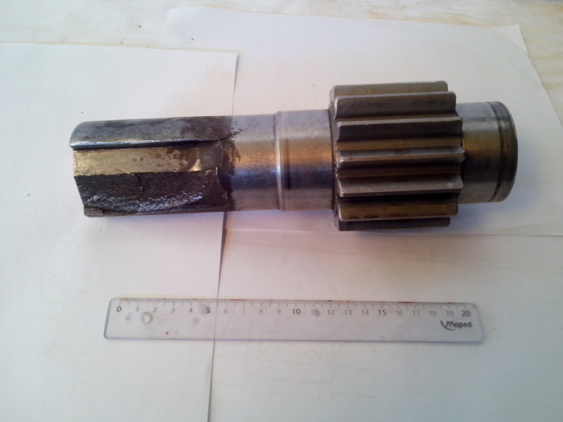
 
The "peeling" type failure shows the key is taking a load; It should not be. See Don Wulpi's book "how things fail" (might not be the exact title).
 
Blacksmith37, I took a look at the book you suggested ("understanding how components fail"), it presents a very interesting example but in this case we can not avoid the transmission of torque through the key unless the axis is redesigned.
 
Every time I've ever gotten a failure involving a free machining steel, the root cause was always improper material selection by using a free machining steel. (Yes, I'm biased but this really is true). Think of the stringers as elongated holes in your steel, because functionally that is what they are. This steel is particularly unsuitable for this sprocket shaft because loading will be along the length of those strings, holes where steel should be. That means much higher local stresses where the metal is coupled with inherent stress risers associated with the crack-like geometry of the stringers.

I suspect that what you think is corrosion product is really oxide generated by fretting, wear between two surfaces. The area surrounding the fracture appears to have been rubbed, indicating possible wear. Corrosion of the fracture would not leave red oxide on the machined surface like your pictures show.
 
GonzaloMartinez said:
Blacksmith37, I took a look at the book you suggested ("understanding how components fail"), it presents a very interesting example but in this case we can not avoid the transmission of torque through the key unless the axis is redesigned.

You appear to have a design problem with your shaft/sprocket connection. So to correct the situation you need to modify the shaft/sprocket connection design. mrfailure points out that the shaft surface degradation is likely due to fretting rather than environmental conditions. Fretting occurs when there is relative motion at contacting metal surfaces. Simply changing the shaft material will not likely resolve the problem.

Keys are a miserable way to transfer torque in a shaft connection. They are only really suitable for indexing purposes. In order to prevent fretting with your shaft/sprocket connection, you need to modify it to have enough of an interference fit such that there will not be any relative movement at the contact interface for the torque force being transmitted.
 
Just a quick dot point not mentioned above.

This fracture pattern is intergranular fracture above along the prior austenite grain boundaries (which is where the sulphide stringers form)

You will also see this pattern in weld sensitised areas of rolled steel.

Cheers,

 
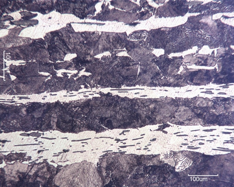
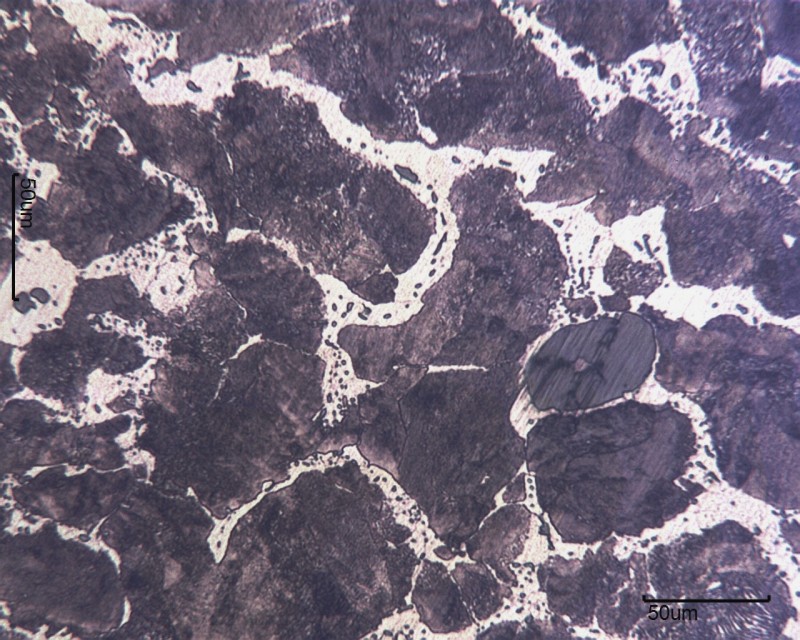
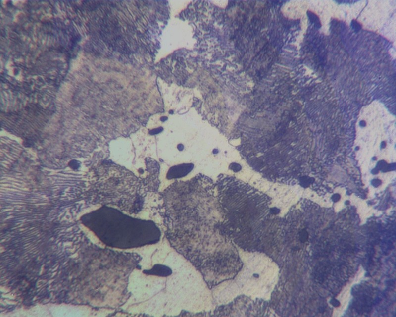
I promised that I was going to post some micrographs so... after having some trouble (I'm taking my first steps on metallography) here they are: Longitudinal and transversal samples, notice the amount of inclusions. It looks to me like ferrite and pearlite, I was expecting to find martensite according to the hardness measured (29HRC average)...... Opinions will be appreciated.

Longitudinal 250X (Dimensional reference is mistaken)

ataque_250x_escala_equivocada_khunlk.jpg


Tranversal 250X

ataque_transversal_250x_xauwdk.jpg


Transversal 1000X

1000x_6_bxcifi.jpg
 
It looks like virtually no reduction after strand casting.
That is banding!

= = = = = = = = = = = = = = = = = = = =
P.E. Metallurgy, Plymouth Tube
 
Status
Not open for further replies.

Part and Inventory Search

Sponsor