Continue to Site

Eng-Tips is the largest engineering community on the Internet

Intelligent Work Forums for Engineering Professionals

  • Congratulations KootK on being selected by the Eng-Tips community for having the most helpful posts in the forums last week. Way to Go!

Sand Casting an air cooled head 1

Status
Not open for further replies.

tdub13

Mechanical
Jan 6, 2012
16
Background: I'm modifying a vintage 2T race engine (porting, intake, combustion chamber etc..) In stock trim, this motor needs better cooling.
I've found a cylinder head (sunburst style fins) that has more mass and more fin surface area, which I want to modify and duplicate in a casting.

I've also found a foundry that will cast this head for me for a minimal fee

My question is around the alloy that they use: 535 ALMAG. I copied this description from
Aluminum alloy 535.0 is an aluminum magnesium alloy that does not require heat treatment to reach full properties. It has excellent corrosion resistance and machining characteristics. Milling and turning speeds are 4X faster than alloy 319.0, and 16 to 18 times faster than gray iron or malleable iron.

The anodizing rating is excellent and the color is satin white after anodizing.

The polishing rating is also excellent and the castings can be buffed to a silvery white color.

The weldability rating is poor and it also is not recommended for leak tight or pressure type applications.

Typically it is used for parts where dimensional stability and shock resistance is important, such as instruments. It is also used for marine hardware, ornamental fittings and castings where lighter weight and high strength is a prime consideration. Almag 35 is 10% lighter than average cast aluminum alloys, 64% lighter than gray iron and 69% lighter than bronze.


My major concern is that it's not recommended for leak tight or pressure type applications. Yikes! The wall of the combustion chamber will be at least 14mm thick. Should I go for it? Or is it a waste of time?

Thanks for any help or opinions! Todd
 
Replies continue below

Recommended for you

I wouldn't for the negative reasons that you stated not to mention how things would change in your high heat and vibration application. There are plenty of good materials that meet your application requirement so using one of those from the start would give you a higher chance of success and allow you to concentrate on the other details of the project.
 
Almag has poor castability. 380 series aluminum might be a better choice.

It is better to have enough ideas for some of them to be wrong, than to be always right by having no ideas at all.
 
Welp... Because I don't fully understand why this material has a bad rating for "leak tight and pressure type applications" maybe I should ask: Why is it so bad? I don't want voids in the casting which would make hot spots. And I'm a little worried about the heat cycle + Pressure from combustion. But for a $free casting, and only one choice in materials at this price, would I be able to overcome this material's shortcomings by making the walls of the combustion chamber thicker? Or anything else I can do to make this work? Thicker walls would help in stabilizing the temp so I think that's going to happen anyway.

Does anyone here know this material's behavior compared to other's?

Thanks again, Todd
 
Sorry, had my diecasting train of thought engaged. 356 or 355.

It is better to have enough ideas for some of them to be wrong, than to be always right by having no ideas at all.
 
When I see not to use it on leak tight or pressure applications that makes me think that it's a brittle material that is susceptible to hairline cracks and other casting defects. This would result in catastrophic failure which is the worse case scenario and I don't see increasing the material thickness eliminating a catastrophic failure from a hairline crack. Material properties are developed from testing and in service performance. To use this material in an application that it isn't good in may require extensive research/development in manufacturing process that wouldn't seem worth it for a one off piece. Even if you could get a perfect and defect free casting the material may still be wrong for the application. You could always do your own pour and have the casting shop that is giving you the good price make the mold. I've melted aluminum at my house many times and can be done fairly cheap.
 
tdub13-

The most common sand cast alloy for engine blocks/heads is probably A356-T6, and A357-T6 has a bit better properties, but both alloys have slightly lower RT properties than A535. However, what matters more are the elevated temperature properties of the materials. The flow/fluidity characteristics of the molten alloy can be a concern when trying to sand cast thin section features like cooling fins. But since your casting has a 14mm wall thickness in the area requiring pressure tightness, I don't see this presenting an issue. You should also take care when designing the mold tool to make sure the cylinder wall surfaces will be free from subsurface defects/porosity that will be exposed after machining.

Prototype qty sand castings are always expensive, even now that there is equipment that can 3D print sand molds directly from a CAD model. So for one or two custom A/C motorcycle cylinders, you might be better off making them using a combination of CNC machining and welding. You mentioned that you require increased cooling from your cylinder design. With A/C two-stroke cylinders/heads, the heat transfer efficiency around critical areas like the combustion chamber is helped by optimizing the conductive heat path from the chamber wall to the cooling fins. So what you want is the minimum practical chamber wall thickness and the highest density of cooling fins on the adjacent outer surface. Increasing the heat transfer area of the cooling fins by simply making them longer is not an efficient way to improve cooling. It is better to keep the fin length shorter, and increase their density by making the fins thinner and reducing the air gap between them. You can get at least two times the fin density using CNC machining that you can with sand casting. Here's an example of what can be achieved with a machined A/C cylinder head (well before CNC machines were available).

Hope that helps.
Terry
 
I've read somewhere in what is now antiquity that superfine head fins, as in a/c cylinder heads similar to the one Terry showed us, were in some cases cut in multiple setups with simple fixtures, using power hacksaws. They didn't even bother to cast the fins; they just cast the heads like elephant feet with ports, and cut away what they didn't need.

The closest I have come to actually doing anything like that is cutting fine slots in an aluminum sheet heatsink blank using a table saw. Woodworking tools work pretty well on aluminum; you just have to beware of the chips, which come off hot and stick to your skin.


Mike Halloran
Pembroke Pines, FL, USA
 
MikeHalloran-

That A/C aircraft cylinder head I linked was machined from a die forging. The cooling fins, intake/exhaust ports, combustion chamber, etc were all 100% machined using 1940s technology.
 
Those fine pitch fins are designed for an application where the is a lot of fast moving air directed over them. A dirtbike engine like this one is going to be slow moving and possibly coated in mud. I don't think the fine pitch approach is appropriate.

----------------------------------------

The Help for this program was created in Windows Help format, which depends on a feature that isn't included in this version of Windows.
 
Wow, Excellent thoughts from all! I don't post much, but really cherish all the great minds that frequent this forum!

This application is a "free air" design in which the air passing by the engine is not forced by a fan or directed by any shrouding. Average Speed is somewhere around 20mph.

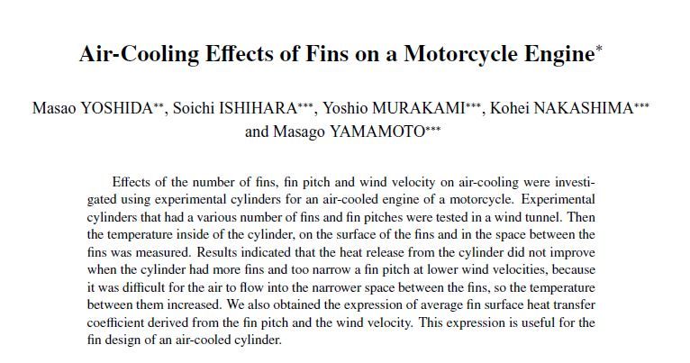
I have a great PDF file that I'd like to share, but don't know how. Here's the Synopsis in JPG format:

Coolingfins_zps9a56d505.jpg


My thoughts, so far:

In this case, The wide fins make sense and having a good draft will aid in transferring the heat to the outer edges of the fins, as well as ease of casting. More mass in the cylinder head will buffer the peaks of the heat cycle in high throttle / low velocity applications such as a long hill climb.

There are some fins which have been truncated at the factory for clearance of other components. These are what I wish to build back to original height. I think epoxy may do the trick for the pattern model. But there are also large voids that need to be filled in (combustion chamber, and on the outside of the chamber). Can I use modeling clay or will that stick to the sand?

Thanks again for all the help!
 
Aluminum cylinder heads for air cooled four stroke engines typically have alloys containing a couple percent nickel. This seems to help high temperature stability. In particular, it helps four strokes retain their valve seats. An old piston alloy, 242, is a favorite.

Modeling clay may be too sticky for patterns and would tend to deform when the pattern is rammed. The softest material I can remember being used in patterns is a hard wax. Pattern makers would take a tool with a ball on the end and use it to form filet radii. This is called 'waxing filets'. You might stop by a pattern shops and ask.

Remember that a casting made from your existing head will have a few percent shrink.

 
I have an old tech paper regarding electronics heat sink design from a Massachusetts tech company.
I seem to recall free air fin spacing needed to be > 1/4" started to prevent viscosity slowing down convection, which is the primary mechanism heat is removed from fins. All typewritten and xeroxed It was an important discovery to me at the time because thermal glass manufacturers were bragging on how their windows with a 5/8" airgap were so superior to those with 3/16" gaps, and even the Shelter institute was advocating a BIG air gap when home building thermal windows.

My fine collection of free air cooled motorcycles seems to support 1/4 inch as a minimum spacing
 
Alloy 242 has a long history of usage for air cooled engine cylinder heads. 355 alloy works as well. 319 alloy with higher silicon content (to where the composition becomes similar to 380 die cast is popular for high volume production of engine blocks/heada at some of the OEMs. I would not consider the 535 Almag.
 
Tmoose said:
I seem to recall free air fin spacing needed to be > 1/4" started to prevent viscosity slowing down convection, which is the primary mechanism heat is removed from fins.
I'm sure that fits in electronics where the heatsinks may be sitting in stagnant ambient air... but did that paper give any info on forced air currents over those fins?

Dan - Owner
Footwell%20Animation%20Tiny.gif
 
Melting down old two-stroke heads might also be a possibility. You could probably assume that the original manufacturers used the correct material.
 
Hi MacGyverS2000,

You asked " did that paper give any info on forced air currents over those fins? "
I don't recall, but I should have been more specific that I believe the scope of the document was vertical fin spacing for free air cooling of stationary objects relying solely on self generating convection.

I suspect the OP is working with bike velocity induced cooling, perhaps with airflow mucked up with fairings and certainly obstructed by frames and wheels and stuff.

Here is the fin spacing that won a few world MX championships back in the 60s. Ground speed on the order of 45 mph or so max and often quite a bit less.
The sunburst style was adopted by the conservative factory and then incorporated on production bikes.

This one came close.

Here is the fin spacing used on the legendary yamaha TZ race bikes in the few days before water cooled heads.
Ground speed a bit higher than the CZ.

Even fan cooled snowmobile fin spacing was fairly coarse. Mostly The fins just got shorter.

At what point die and sand cast manufacturing, optimum fins size and spacing for cooling, or some other thing set the dimensions is comPLETEly unknown to me.
My first and perhaps final thought would be, it worked fairly well for them.
 
Fundamentally, the 1/4 spacing seems sound. A "Tesla" turbine, as I recall, is nothing more than closely spaced plates (sans blades or fins) on which the medium acts, via viscosity/friction of the flowing medium.

It is better to have enough ideas for some of them to be wrong, than to be always right by having no ideas at all.
 
Thanks for all the replies! I've contacted the foundry foreman and asked about hard wax and also the possibility of melting down some heads and cylinders that I have. I'm wondering if melting down pistons would be a good choice of material, assuming that pistons would be a different alloy than cylinders and heads. They are more abundant for sure!
 
The pistons are generally a hypereutectic alloy which require special molds, casting, and cooling techniques.

----------------------------------------

The Help for this program was created in Windows Help format, which depends on a feature that isn't included in this version of Windows.
 
Status
Not open for further replies.

Part and Inventory Search

Sponsor