Continue to Site

Eng-Tips is the largest engineering community on the Internet

Intelligent Work Forums for Engineering Professionals

  • Congratulations KootK on being selected by the Eng-Tips community for having the most helpful posts in the forums last week. Way to Go!

Sand Casting an air cooled head 1

Status
Not open for further replies.

tdub13

Mechanical
Jan 6, 2012
16
Background: I'm modifying a vintage 2T race engine (porting, intake, combustion chamber etc..) In stock trim, this motor needs better cooling.
I've found a cylinder head (sunburst style fins) that has more mass and more fin surface area, which I want to modify and duplicate in a casting.

I've also found a foundry that will cast this head for me for a minimal fee

My question is around the alloy that they use: 535 ALMAG. I copied this description from
Aluminum alloy 535.0 is an aluminum magnesium alloy that does not require heat treatment to reach full properties. It has excellent corrosion resistance and machining characteristics. Milling and turning speeds are 4X faster than alloy 319.0, and 16 to 18 times faster than gray iron or malleable iron.

The anodizing rating is excellent and the color is satin white after anodizing.

The polishing rating is also excellent and the castings can be buffed to a silvery white color.

The weldability rating is poor and it also is not recommended for leak tight or pressure type applications.

Typically it is used for parts where dimensional stability and shock resistance is important, such as instruments. It is also used for marine hardware, ornamental fittings and castings where lighter weight and high strength is a prime consideration. Almag 35 is 10% lighter than average cast aluminum alloys, 64% lighter than gray iron and 69% lighter than bronze.


My major concern is that it's not recommended for leak tight or pressure type applications. Yikes! The wall of the combustion chamber will be at least 14mm thick. Should I go for it? Or is it a waste of time?

Thanks for any help or opinions! Todd
 
Replies continue below

Recommended for you

Aha, Yes now I remember. Hypereutectic meaning the alloy has a high melting point... It's beyond the eutectoid football shape on the graph. It's been a while but I remember the graph!

Time to start gathering up all my doorstops. :)
 
With aluminum casting alloys hypereutectic typically implies a silicon content above 12%. There are some sand casting aluminum alloys that have a silicon content above 12% (like A390). Using scrap pistons as your raw material would not be a good idea, since you would have no idea what the piston alloy was composed of. Most auto engine pistons are either die cast or forged, and the alloys used are not suitable for sand casting. It is important to know exactly what the composition is of the alloy you are using for your casting. In order to achieve the desired properties you need to use a specific alloy designed for the particular casting process you will use. Also, the pattern maker will design the mold for using a specific alloy based on its characteristics like shrinkage, hot tearing, fluidity, etc.

In reality, the raw material cost will not be a huge factor in the price of your casting. If the trimmed casting weighs say 10lbs, then the amount of metal that will be poured would be something like 20-25lbs. The cost of aluminum casting ingot is probably not much more than $5/lb, so the material cost for a casting should be less than $150. And the raw material cost will be modest in comparison to the cost of constructing and preparing the mold tool.

Good luck to you.
Terry
 
The preceding posts give good advice. I agree that an alloy commonly used for air cooled heads should be used. 356T6 is common. The essential property is the strength at high temperatures.

14mm chamber wall thickness seems on the thin side. Thick, solid aluminum is strong and a good heat spreader. The larger the area of fin base the more fins can be accommodated. The base is larger with a greater wall thickness. The only way to increase cooling over the existing design is with more fin area, so this suggests more fins on a larger fin base and longer fins.
 
Some of the photos linked by Tmoose provide examples of how to improve heat transfer efficiency with an AC motorcycle cylinder. The MJC example shows fins that have "joggles", and the purpose of these joggles is to trip up the boundary airflows, which increases the heat transfer rate between the fin surface and the cooling air. The Yamaha TZ example shows slots in the fin edges which creates a similar effect by mixing the core flows.
 
Here is a pretty typical example of cooling and basic intercooling of an air compressor. Both are in essentially the same airflow coming from the bladed pulley/sheave.


The tight fin spacing on the HOT intercooler line is in contrast to the cast cylinder fins. My hunch that may be due as much to the differences in manufacturing methods for each component as the cooling requirements.
 
Hi Tbuelna, I can not say with certainty the reasons for joggly fins and cut fins, but reduced radiated noise and reducing bore distortion when hot were considerations for US street bike markets and race bikes of the era.

regards,

Dan T
 
The Montesa fins look pretty "trick". I do recall that during testing, the magazines mentioned that the fin design was superior in collecting and holding dirt and mud. (not good) :) I'm intrigued by the cuts in the fins on the TZ cylinders. It appears to be more of a mechanical resonance breaker, but I can imagine the cuts may entice airflow deeper into the fins than without the cuts. I may consider this design feature by machining after casting. But it does bring noise into question:

Mechanical "noise" is at least a small design factor on these bikes: Nobody wants to hear the "jingling" of the wrist pin bearing amplified. My bikes need to pass a sound test at tech inspection. There are a few different ways to combat engine noise and "fin rattle" that I've seen, but they all seem to be Band-Aid approaches. Yamaha frequently uses rubber dampers between the fins of their cylinders and on the heads, they bridge the fins with the casting, as seen at the top of this thread. I'm not sure what to do here: I'm also wondering if my design (more taper in the fin, larger root width) will aid in keeping the fins from becoming sounding boards for the bearings and combustion.

Thanks everyone for your thoughts and comments. I really appreciate all the help with this project! I'll post pics of my pattern as soon as I get something nice to look at.
 
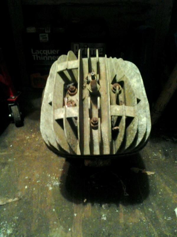
Before:
79YZ250Head_zps23a8d28d.jpg


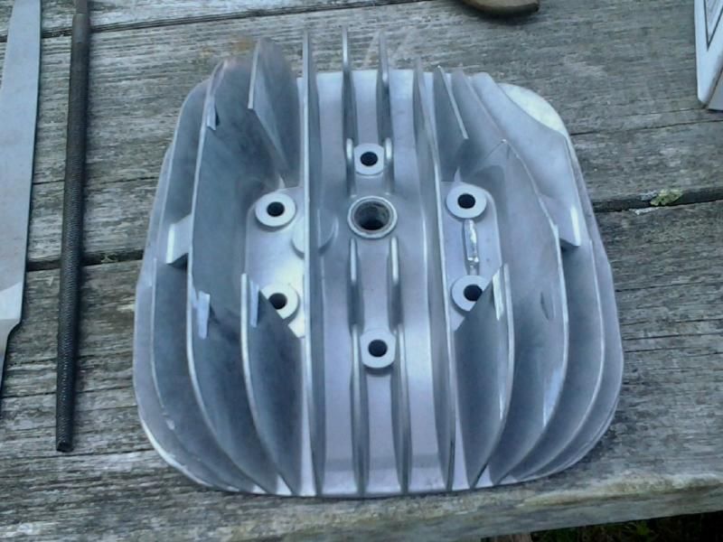
First steps. Clean and cut the webs out. Parting line will be centered behind the middle remaining webs and over the spark plug area. These webs may be continued across the entire head.
79YZ250Head2_zpseb5facb6.jpg
 
It's interesting that the area of the head with the highest thermal input (ie. around the combustion chamber and spark plug port) also has the least efficient heat transfer path to the cooling airflow.
 
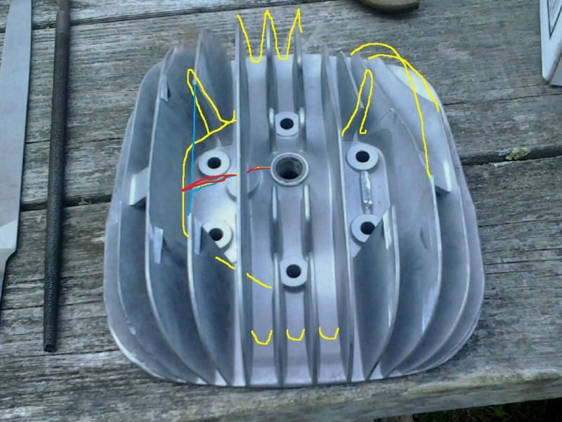
Agreed 100%. This is what I aim to "fix" before casting. In the terrible paint pic below, if you use your imagination and patience with my bad "art". I've tried to show where I'm adding material to the top side of the chamber, especially as it loses altitude going away from the sparkplug. I'm going to attempt to fill in the concave curves and make the entire thing a nice convex dome.

I also want to widen the root width of the fins. I plan in using a popsicle stick to create the radius at the bottom of the fins. Hopefully I can extend the fins a bit to regain the surface area that will be lost.

I'll also rebuild the fins that got truncated at the factory to clear the pipe. And connect the fins that were cleared in the middle for the studs. So, all the fins will be continuous and I will be able to machine the sparkplug hole and stud locations wherever I need them to be.

79YZ250Head3_zpsa1f9c55a.jpg
 
 
Always wanted one of those Maico 490's, I was riding 125's in those days. Later I did have a CR500 with proper water cooling, that thing was a monster. 5th gear wheelies were easy. Everyone I let ride it broke a bone.

----------------------------------------

The Help for this program was created in Windows Help format, which depends on a feature that isn't included in this version of Windows.
 
My YZ490 is the same way. I don't let anyone ride it. The YZ125 is a great bike and it has a lot of untapped potential in the porting and combustion chamber design. In vintage MX racing, we're not classed by displacement, only by year and technology: The EVO class around here is for drum brakes, air cooling and non-linkage suspension. I've won just as many races on my 125 as I have on the 490! I like building the bikes and motors because there's gobs and gobs of performance improvement that can be enjoyed by the builder.
 
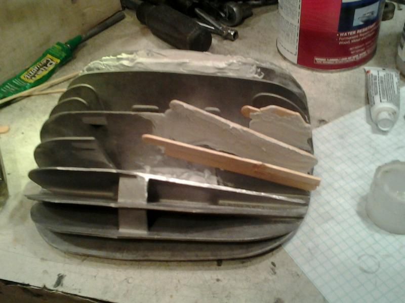
I've finally gotten back to this project. Old School pattern making in process. Wood, bondo, spot putty and a lot of massaging to go. Here's what it looks like now. I'm building up the truncated fins, then extending all the fins and adding mass over the combustion chamber and flowing it out towards the edges.

79250headmodified1_zpsde59f8b7.jpg
 
RR350 (LM119) developed for use in Piston Aero Engines by Rolls Royce and has good high temperature properties.

Solution treat 540 degC for 6.5 hours quench in boiling water and the age for 16 hrs at 215 degC
 
Thanks for the tip! I will look it up.
 
tdub13-

Why go thru all of this trouble when you can design and optimize your head using 3D CAD and FEA? And then have it made using DLMS in almost any aluminum alloy you want? If you limit yourself to using sand casting for this head then you are restricted to using aluminum alloys that have lower mechanical properties.

When it's all said and done, the cost of using DLMS won't likely be much different than the total cost of having the head sand cast.
 
Status
Not open for further replies.

Part and Inventory Search

Sponsor