Just Some Nerd
Structural
Hey all, needing some more experienced eyes on this one.
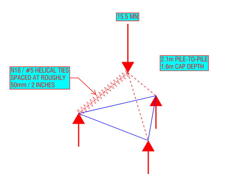
My company has a relatively large RC structure we're in the process of designing right now, ~30 stories of residential. I've been working on developing an SMath sheet with strut and tie calcs for the 3 & 4 pile caps, which isn't too complicated to sort out in terms of calculation but can produce some pretty heavy results when it comes to assessing bursting reinforcement. As an example of loads, worst case ULS load for a 3-pile cap is about 15.5 MN, so fairly large loads. Pile arrangement is an equilateral triangle (2.1 metres pile to pile) with reinforcement being laid in 3 directions for simplicity so no concerns there, and some decent depth to the pile cap (1.6m depth or thereabouts at the current sizing). My company has dealt with pile caps before, but not on a scale that's had to deal with bursting reinforcement before, which is where you all come in hopefully.
It's been mentioned on older threads on this forum the slightly counterintuitive situation in that bottle-shaped struts don't work quite as well as a set of prismatic ones would, but Australian Standards (rightfully given how struts will likely behave like in reality) doesn't allow assuming prismatic struts where not limited by geometry.
My question to you all relates to the amount of transverse reinforcement typically provided for such a scenario as this, and how it would be detailed for constructability. So far we're just imagining circular/helical ties along the length of the struts - picture the three struts as reinforced columns between the piles and base of the tower column. Providing the transverse bursting reinforcement in some other manner seems like an absolute mess to construct and police on-site, but would be keen to know if there's any good alternatives out there. For serviceability conditions, we're getting results like N16 helical ties (#5 bar I believe) being spaced at a little over 50mm (2 inches), and I'm wondering if that sort of number makes sense to you all. Increasing the depth of the pile cap has some effect, but we're trying to limit that due to the relatively loose sandy material at the site.
Little bit of a diagram for you all
----------------------------------------------------------------------
Why yes, I do in fact have no idea what I'm talking about