Continue to Site

Eng-Tips is the largest engineering community on the Internet

Intelligent Work Forums for Engineering Professionals

  • Congratulations GregLocock on being selected by the Eng-Tips community for having the most helpful posts in the forums last week. Way to Go!

screw thread stripped out

Status
Not open for further replies.
hi,
We have a screw-plug(forgive me my poor English) fractured after about one year in use. the location of the fracture is at the fillet . after disassemnlying the transmission, it was found that the screw thread was completely stripped out as the below photo shows(this is another failed part, and is similar with the fractured one).
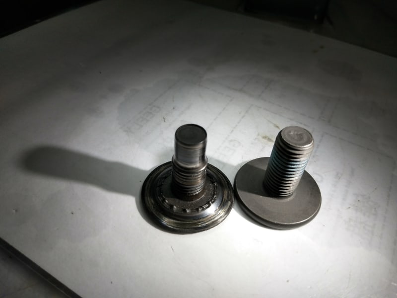
IMG_20191219_092633_hwinus.jpg

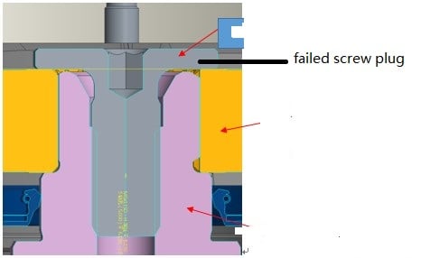
Below photo shows you the fracture surface and the assembly schematic diagram.
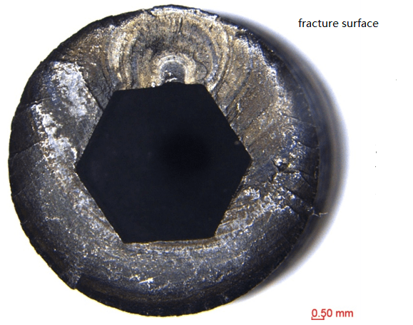
fracture_surface_t7v4ek.png

assembly_drawing_phmsrq.jpg

The fractured part’s microstructure,HV and its tightening curve were all examined ,and all of them are OK. and also no decarburization was detected.
my question is how this failure happened and what made the screw thread stripped? Can anyone give me some light on it and request your suggestion.
thanks in advance.
 
The head is too thin, the hex too deep, and the radius too tight for my taste.
Those marks are clearly fatigue. You likely simply exceeded the limits for the material.
As cleanly as they striped I am guessing that it is rather soft, and that will also give it low fatigue resistance.
What does it screw into?
What load is on it?

= = = = = = = = = = = = = = = = = = = =
P.E. Metallurgy
 
Both types of failure occurred in the same part ?
 
@EdStainless (Materials)

What does it screw into?
motor shaft, and its surface hardness of the internal screw is about HRC60, nitriding processed.
What load is on it? tigtening curve below:
https://res.cloudinary.com/engineering-com/image/upload/v1577405619/tips/T181108A0895%E8%9E%BA%E5%A0%B5%E6%8B%A7%E7%B4%A7%E5%AF%B9%E6%AF%94%E6%9B%B2%E7%BA%BF_qjl1ng.pngthe the max. torque is about 45N.m, and according to the supplier's expericence, the clamping force should be about 12KN.
and we also found that there is oxide defect(EDS test result) in the tip of thread, as shown below:
[img [URL unfurl="true"]https://res.cloudinary.com/engineering-com/image/upload/v1577406657/tips/teeth22_hz4nlg.jpg[/URL]
 
Could the threads have stripped during installation due to improper alignment or cross-threading? That would have prevented complete tightening (allowing greater cyclic stress initiating fatigue), and also increased loads on the remaining threads.
 
If those are high temp oxides then the cracks formed after threading and prior to or during heat treatment.
Are the treads rolled?
What HT is done after threading?

= = = = = = = = = = = = = = = = = = = =
P.E. Metallurgy
 
@mrfailure (Materials)27 Dec 19 15:39
Could the threads have stripped during installation due to improper alignment or cross-threading?
no, it was not happened duiring installation, it was happened one year after installation.
 
It looks a lot like the shaft broke at the shoulder, leaving the threads at the end carrying the load, but since the tension in a fastener is taken closer to the entry, those threads had no tension on them and eventually wore smooth. Lacking tension on it, the orange part was free to chew up the underside of the screw head.

If that's not the case then it was magic or a lot of other details have been left out, like pictures of all the other parts and what the load paths are.
 
It seems to me that if the fatigue cracking first occurred at the shoulder under the head (I think that is what I'm seeing in your photo), then load would be taken off of the threads as it all concentrated on the shoulder until fracture occurred. The example photo of another failed screw shows stripped threads but not a fractured screw, yes? It makes the most logical sense for the threads to first strip, reducing the total clamping load on the screw. This may allow the screw to start backing out, allowing higher cyclic loads under the head. Because fatigue is progressive, it would have taken you a year before fracture finally occurred after crack propagation.
 
Concur with input, so far. But I have a few questions.

What threads on the pin and hole? Have you go/no-go gaged these threads? How were the male thresds made: cut or rolled?

Have you verified the fillet radius. Is the fillet radius 'rolled'.

What is the Assy torque? Do you use lubricant or antiseize compound?

Is the pin internal hex made by forging/finish-broaching: or by drilling and then step-broaching? Have you validated the internal hex dimensions?

Caution: high strength steel must be heat treated and cool-machined to avoid blue-brittle condition. Is there any evidence of blue (blue-gray, blue-brown, blue-purple) coloration anywhere?

A shallow head pin like this requires a shallow drive recess: internal-hex, Phillips, Torx, etc. Some permanent installed pins like this could benefit from an integral/protruding 'stud-drive' designed to shear-off flush at a 'set-torque'... leaving the head 'solid'.


Regards, Wil Taylor

o Trust - But Verify!
o We believe to be true what we prefer to be true. [Unknown]
o For those who believe, no proof is required; for those who cannot believe, no proof is possible. [variation,Stuart Chase]
o Unfortunately, in science what You 'believe' is irrelevant. ["Orion", Homebuiltairplanes.com forum]
 
Status
Not open for further replies.

Part and Inventory Search

Sponsor