Eng-Tips is the largest engineering community on the Internet

Intelligent Work Forums for Engineering Professionals

Seismic design of moment-resisting concrete frames with embedded pedestals

Status
Not open for further replies.

Antidude90

Structural
Feb 9, 2024
13
0
0
CO
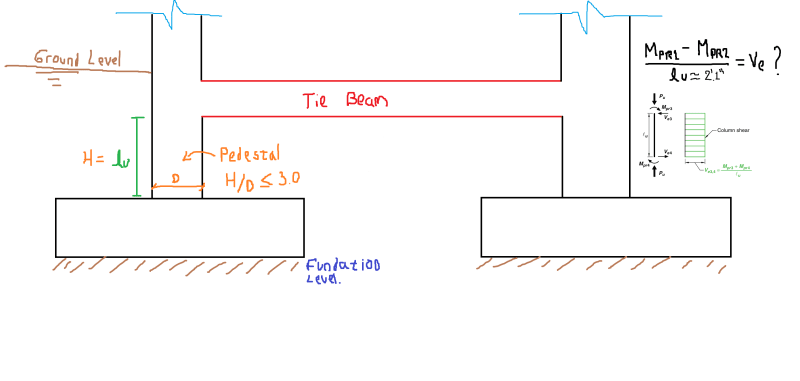
I have a moment-resisting concrete frame structure located in a high seismic hazard zone. At the base or ground level, I will place a tie beam that will be connected to pedestals (or fully buried column sections that allow the foundation level to be reached) (see attached image).

Considering that the pedestals comply with the H/d < 3.0 ratio, and taking into account the provisions of ACI 318 18.2.2.3, which states that "any element below the base required to transmit seismic forces must comply with the provisions of Chapter 18", I'm wondering follow:

- Should the pedestal be considered as an element subjected to axial load and bending, as those defined in 18.7?
- If so, should the design shear force (Ve) be satisfied, as described in 18.7.6.1, where the shear force must be calculated considering the maximum probable moments at the faces of the joints and the unsupported length of the pedestals!!!?
- In my opinion, it is not necessary to calculate the design shear force in the pedestal as if it were expected to dissipate energy. Because the pedestal, being buried and having a low H/d ratio (less than 3), behaves more like a rigid body than a flexible element. Also,the main function of the pedestal is to transmit the axial force of the column to the ground and the shear force transfer between the pedestal and the ground is mainly done by friction. In my experience, I have designed pedestals in this way without performing the design shear force calculation as defined in 18.7.6.1, and I have not found any problems.

Pedestals_tytizv.png


I appreciate any comments or suggestions you may have regarding this.
 
Replies continue below

Recommended for you

Ok, I feel like I'm getting my head around this now. Definitely one of those jobs that would be a lot faster and easier to discuss over a cup of coffee at a work desk!
So the argument of the tie beams is that they're just there to give axial tension/compression to brace the columns, and that their dimensions are so small relative to the main beams that they have minimal impact on the overall structural performance?
I do understand why you might consider leaving them out but personally, I'd still model them in, as they will exist and will attract load and will change your performance slightly
They will attract some moment in particular so you want to make sure that the tie beam is appropriately reinforced for the moment + axial combination

Now I understand your point more about the pedestal reinforcement
I think using the phrase 'pedestal' is a bit misleading really, as these things are either columns or heavily axially loaded walls, which are basically columns in Code's eye anyway
So I dug up our code provisions for columns that are protected against plastic hinging
Screenshot_2024-05-15_084719_ials07.png

So basically, you still have to protect the hinge zones in the column regardless
However, our code has different levels of ductile detailing - we have 'limited ductile' (up to ductility 3.0) and 'ductile' (up to 6.0)
The required transverse reinforcement in the hinge zones is the minimum of 'limited ductile' for bar buckling or 70% of 'ductile' detailing requirements for concrete confinement
But this provision doesn't apply to the lower levels - so your 'pedestal' would be required to have full ductile detailing in the hinge zones

So, tl;dr your code's requirements match my own Code's
 
I think the fundamental thing here is if you want the flexural failure to occur in the frame as you want - everything else needs to survive until them. You back out the Ve based on Mpr to protect your frame against shear. If the other elements supporting the frame will fail before Mpr or Ve [of the frame above, not the things below the frame] - then they are failing before your desired locations are.

It's like connection detailing in steel for seismic bracing - bolts are designed to the capacity limit of the member or using an overstrength factor. You make the connection more "rigid" by needing to bump up your bolt sizes...weld thickness, etc. to amplify capacity. Do whatever you need to do to the system to ensure what you want to happens actually happens.
 
Greenalleycat said:
... So basically, you still have to protect the hinge zones in the column regardless
However, our code has different levels of ductile detailing - we have 'limited ductile' (up to ductility 3.0) and 'ductile' (up to 6.0)
The required transverse reinforcement in the hinge zones is the minimum of 'limited ductile' for bar buckling or 70% of 'ductile' detailing requirements for concrete confinement
But this provision doesn't apply to the lower levels - so your 'pedestal' would be required to have full ductile detailing in the hinge zones

Yes, I completely agree, the tie beam, no matter how small it is, will assume some moment, but obviously the reinforcement that one has (minimum), must be able to assume that demand for forces, or that is what I have been able to deduce from the times I have modeled such elements.

In the ACI318 code, we also have something similar ACI318 18.4.3 (Columns), but this applies to Intermediate moment frames.... in the Special Moment Frames section, this option does not exist, and the requirement is clear, in stating that a shear associated with the plasticization moment of the section must be guaranteed. It is a normative discussion, or now I am starting to believe it so.

In addition, as you say, it applies to elements that can achieve plastic hinges. In this case, a fully buried pedestal, with a response similar to that of a rigid body, would not present this condition, or that is what I personally believe, with my limited knowledge on the matter.

thanks for reply
 
Luceid said:
I think the fundamental thing here is if you want the flexural failure to occur in the frame as you want - everything else needs to survive until them. You back out the Ve based on Mpr to protect your frame against shear. If the other elements supporting the frame will fail before Mpr or Ve [of the frame above, not the things below the frame] - then they are failing before your desired locations are.

It's like connection detailing in steel for seismic bracing - bolts are designed to the capacity limit of the member or using an overstrength factor. You make the connection more "rigid" by needing to bump up your bolt sizes...weld thickness, etc. to amplify capacity. Do whatever you need to do to the system to ensure what you want to happens actually happens.

This argument is practically my structural design concept. I define that frames or elements would function as fuses (dissipating energy through damage or plastic hinges), ensuring that the other elements are capable of transmitting forces to these elements (elastically) and thus ensuring that everything works. Now, imagine that you have several frames and that the code forces you to use seismic connections, in elements that you do not intend to fail, but to transmit seismic forces to your fuses. That would not be logical, and it is something similar to what happens to me with the pedestal... the code forces me to detail it as if it were an element that is going to function as a fuse, when in reality that does not happen.
 
Status
Not open for further replies.
Back
Top