Continue to Site

Eng-Tips is the largest engineering community on the Internet

Intelligent Work Forums for Engineering Professionals

  • Congratulations KootK on being selected by the Eng-Tips community for having the most helpful posts in the forums last week. Way to Go!

Seismic performance of infill frames 3

Status
Not open for further replies.

Blackstar123

Civil/Environmental
May 5, 2013
253
This is a question that always pop into my mind when I see a 10+ story RCC building, with all stories filled with masonry infill walls except those floors which are reserved for parking.
How do they take into account the effect of masonry infill in the seismic analysis of the frames?

My major design experience is in cement plants which mostly don't have frames with infill walls. So if someone have designed tall buildings, i would really appreciate if they will share their design practices.

Euphoria is when you learn something new.
 
Replies continue below

Recommended for you

On a basic level, you have two types: contributing and non contributing. If they are contributing, then the wall is in firm contact with the frame and is essentially designed as a shear wall - the shear transferred from the frame to the wall is, more or less, dependent on the deflection compatibility of the two. If they are not contributing, there is a gap (usually filled with a compressible material) between the frame and the masonry. The frame deflects under lateral loads, but is not permitted to touch the infill panel and so the infill panel is just along for the ride.

I haven't done much of this kind of design myself, so I'm afraid I can't shed any more light on particulars.
 
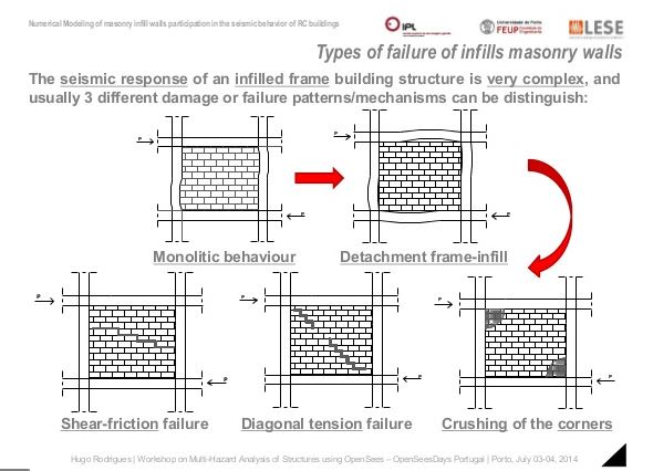
When the masonry is contributing structurally, as designed or by accident, you get the formation of the mechanisms shown below. Primarily, the masonry forms a corner to corner strut across the frame bays.

If you're interested in a deep dive on this, you can find that in the book below where they cover it at length, both in terms of the potential problems and, also, in terms of the successful use of the system in one and two story structures found in high seismic areas of the industrial world.

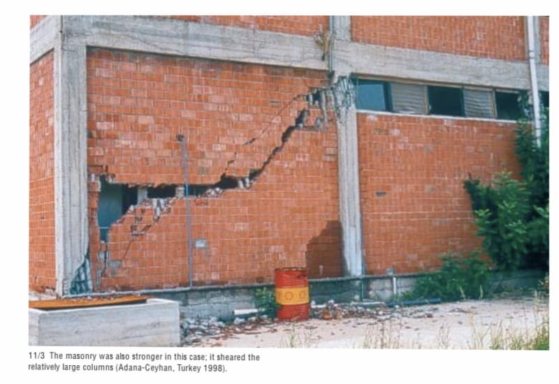
In my opinion, structural reliance on this mechanism should be limited to one and two story buildings. Even at ten stories under wind alone, you can easily get to the point where the masonry infill failure modes shown below start to manifest themselves.

c01_fxnuue.jpg

c02_e849br.jpg
 
I would imagine it would depend on the era of the building if the infill was designed as part of the lateral system (older buildings didn't really do seismic design). As phamENG said the main thing is how the infill is detailed and if it's participating or non-participating. In other words if the building frame deflects is the infill wall engaged? The masonry code TMS 602 (previously ACI 530) has empirical design requirements for masonry infill including the required gap if the infill is non-participating.
 
[In my opinion, structural reliance on this mechanism should be limited to one and two story buildings. Even at ten stories under wind alone, you can easily get to the point where the masonry infill failure modes shown below start to manifest themselves.]
Correct me if i understand this wrong. What i get from this is that infill bracing effect will diminish once the wall is cracked.

Euphoria is when you learn something new.
 
Correct. Just as the stiffness of a concrete beam is reduced past the initiation of cracking, so do masonry walls/assemblies.
 
Edub24 and phameng
Lets say infill wall is in complete contact with the frame and i want to design my frame for this condition. Then how should i model it in computer.

I've seen constructions site where masonry infill is being used as supports for beam shuttering.

Euphoria is when you learn something new.

 
KootK thank you for book suggestion.

Euphoria is when you learn something new.
 
Nice link, bones. Blackstar - how you model it will depend on the program you're using. Before you try it, though, run through the procedure in bones' post by hand to get a feel for how it works. Once you understand it and confirm the results make sense, look at your modeling program's documentation for directions on modeling it. Run a couple simple ones to match what you did in your hand calcs, and make sure they match. If they don't, figure out the source of the error (often in how you modeled it), and adjust until you've mastered the concept, the manual calculations, and the computer simulation. If you try to jump straight to the computer simulation, you're doing engineering wrong.
 
I recently designed a RC frame building with participating reinforced 12” CMU infill in a non-seismic area. The bare frame worked fine for strength but I was forced by the code to consider the CMU struts. The code-mandated struts failed miserably under wind load. It also doesn’t allow you to consider any wall panels with openings, which was almost 100% of my walls. It also doesn’t allow you to consider the infill reinforcement. It also prohibits any in-plane connection between the infill and bounding frame, which effectively prohibits one from using reinforced CMU detailed in a traditional way.

In the end, I decided to ignore the infill part of the code and designed it as a bare frame without consideration of the CMU for stiffness or strength. I felt comfortable doing this since:

1) non seismic area with a long history of good performance with this type of construction.

2) talked to code officials and CMU industry groups in the area and none of them were remotely aware of the new infill code appendix.

3) the new code requirements seem like they were added without full consideration of the ramifications to traditional/practical design.
 
Bones said:
It also prohibits any in-plane connection between the infill and bounding frame...

Interesting. Did the literature express a rationale for that? Predictability? Shearing the wall apart?

Did you get far enough down the path that you evaluated the impact on the bounding frame? They mention that in the article that you cited without getting into the meat of it. With respect to seismic in particular, I've always been curious to know if these things wind up being problems:

1) Shearing off the columns where they meet the floor system (shear friction).

2) Punching shear from the strut vertical component pushing up/down on the slab (perhaps beams are a universally good idea for this).

It's always struck me a proportionally out of whack that you'd collect seismic load like a brace/wall and then shove that load through a column-beam joint.
 
I think the issue is that the shear force concentrates at the dowel joints and destroys the masonry locally before the strut mechanism can develop. It drives you to use clip angle type supports for out-of-plane only. I think there is an out in the commentary that says in-plane connectors with “sufficient ductility” can be used. My hypothetical argument in court would be that I don’t need ductility in a non-seismic area so rebar dowels are ok. Kind of a weak argument though since winds can also generate huge forces and drift.

I did beef up the columns and beams for the amplified shear from the struts. That is covered pretty explicitly in the code appendix, but makes analysis tedious. You wind up with multiple sets of load combos that only apply to shear or bending of columns or beams. It’s a lot of bookkeeping.

I think they are planning to add provisions for walls with openings in the next code cycle. Maybe then the code will be more applicable to real world designs. They need to add considerations for masonry reinforcement and exceptions for non seismic areas. Then it will be ready for prime time.

Generally it seems like the worst kind of construction for a seismic area. High mass and low ductility, producing heavy falling rubble. So unfortunate that it’s the predominate construction in many parts of the world with high seismic risk.

 
phamEng, I cannot agree more with you.

bones206, Great link. It explains the mechanism in simple and precise manner.
I just have one difficulty in understanding the following statement.
image_spev0q.png

How can the partial infills have more stiffness than infills with no opening? And if partial infills attract more load than complete infills, than won't it be unsafe to not consider the added stiffness in the analysis?

KootK said:
It's always struck me a proportionally out of whack that you'd collect seismic load like a brace/wall and then shove that load through a column-beam joint.

Yes i agree that it will be better to provide joint detailing in such a way that infill do not provide any support to the frame. But as far as I've seen the construction practice where I live, no special joint detailing is being considered to isolate the infill from frame.
I once talk to a fellow engineer from a consultancy firm specialized in designing 10 to 15 stories building and ask them the same question that if they consider infills in seismic design. The answer was No and the reason they give me is that once the wall is cracked it looses its stiffness.

But my concern was and still is, what if the joint fails before wall is cracked. And not to forget the bottom 2 to 3 stories for parking which do not have infill. Won't it perform like a soft story during seismic event?

Euphoria is when you learn something new.
 
Blackstar123 said:
How can the partial infills have more stiffness than infills with no opening? And if partial infills attract more load than complete infills, than won't it be unsafe to not consider the added stiffness in the analysis?

The wording is a little confusing, but I don’t think they meant partial infills have more stiffness than full infills. They are just saying that the partial infill attracts more shear to the column relative to a bare RC frame without infill, yet doesn’t provide any beneficial stiffness as a lateral load resisting element. I imagine a shallow strut develops at small drifts, which spikes up the shear force in the column, then the infill fails brittlely at higher drifts and provides zero ultimate lateral resistance. I believe these effects are well accounted for in the TMS 402 Appendix B code provisions.
 
Hello,
Please also read : I am glad that this topic is discussed here because in my opinion the nonstructural elements made from masonry (infilled walls or the walls that are between slabs without rc frames) are the most vulnerable part of a building during an earthquake. I think it's more probable that a masonry partition wall will fall (and have a great risk of killing people) vs a new designed RC structure to collaps.
In my area seismic design code is specified that you should only consider the negative effects of the masonry partitions - like global torsion, soft story's etc.
Also as the structural engineer of the RC building you have to check for the stability and capacity for all of partitions. There is a big problem here: you can check the infilled walls for out of plane forces (seismic force perpendicular to the wall or wind) and for in plane forces (modelling with diagonal struts and check the limits) but for walls that are not infilled how to do you design for the interaction with the RC structure ? This is clearly specified in my code that you should check for the interaction with the building deformation...
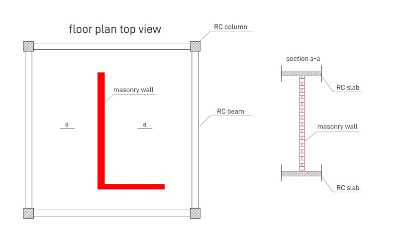
Say for example that you have the story drift on 1%. For a 3m level there will be a lateral movement (drift) of 3cm. Lets say that we have the case from the picture below - in the left is the floor plan and in the right is a section trough the masonry wall represented with red color :
p1_utscsf.jpg

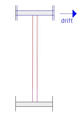
Now if the earthquake happens and we have a drift of 1% the top slab will move 3cm left/right. What happens with the masonry wall ? It will drift (shear+bend) on top with the slab 3 cm ? I dont think so because if you calculate the necessary force in order to displace it 3cm the force is huge and the wall can't take it.
p4_e1bigv.jpg

So it's clear that something has to break... I think that the shear connection (the mortar) between the slab and the wall (the top contact surface) breaks and the wall will not have any more the imposed displacement on top from the structure but only the seismic force from its on mass. If this is the case in my example because top end of the wall (top as you look at the plan) its free (the bottom has an perpendicular wall so lets say this end is fixed) and now the connection with the slab is gone its a very bad situation because as you look from the side of the wall top is free, left is free, bottom and right simple fixed.. Bending capacity is reduced to almost 0... what do you do then ?
Option 1. Use near the slab and wall connection steel angles.. Yes this is good for calculating bending out of plane because the top is fixed BUT then the 3 cm displacement is for sure transmitted (imposed) to the wall.. the wall cant bend that much, what happens then ? I think that the bricks that are in contact with the steel will break from pressure.. and then we are back to start with no connection on top and a great risk of instability.
Option 2. At the free end of the wall (as you look at the plan: on top) make a small RC column fixed bottom and top with a dowel so that can take only shear.. Now the elevation of the wall is : bottom, left, right fixed and top free. It's better but as the column is fixed to the slab it will deform with the structure.. the key thing (I think) is to use a very soft dowel so the slab movement will not induce a 3cm top displacement of the column rather a smaller one (by bending of the dowel). If you can solve this on paper maybe it's a good choice but to execute it (build it) to perform this way is tricky...
Option 3. I don't know, maybe you have some ideas...
Btw this is also a problem for the infill walls ...

This is only a small example, there are many cases like this that are difficult to solve (if they are solvable).. This is why I think that masonry partitions are the greatest danger in case of an earthquake, especially because in my area the architects practice thin walls (15cm), 3 m height and God know how long (3-6m)...
Any input on this topic will be great, thank you and btw Hi KootK.
 
Akee said:
Any input on this topic will be great, thank you and btw Hi KootK.

Hi yourself Akee. It's good to have your input on this one. With regard to your comments and questions:

1) I agree and see only two viable solutions:

a) Isolate infill walls from story drift movements at the topside wall to slab connections OR;

b) Consider the impact that the presence of infill walls will have on the structure, both globally and locally.

2) Your point about wall returns is an interesting one. One way around that would be to interrupt wall continuity around the corners of those walls so that no wall ever actually had a return in the structural sense. Vertical wall movement joints. However:

a) There would be implications to cost.

b) There would be implications to fire protection in some cases.

c) To my knowledge, this isn't currently being done.


Ha, what you are saying its not that simple.
1.a - how do you do that ? I described 2 options but none is very good. Making on top of the wall a free end with the slab (2-3cm gap filled with deformable material) it's kind a risky ... why ? because you lose the arc effect, the only thing that holds the wall not to fall over.. so if you do it you better be very sure about it... (a wall that stays on 10th story slab with top, left and right free unpinned its a very dangerous stuff..
1.b - again, how do you do that? using FEM i guess, but how ? modelling all interior walls as a wall element and mesh them? for a 3000 sq m building good luck with that, haha.. But even if I do that I dont think that will work.. putting a wall over a slab element will not model the reality with masonry over concrete.. If you have an idea how to model this I would be happy to try it.

2 - hmm .. wall returns are very good for making that edge fixed (pinned on vertical edge).. so for perpendicular action on the wall I will rather have a fixed end the a free end..
 
I think we give arching action too much credit in a seismic scenario. The building is bouncing around side to side, up and down, twisting, and all possible combinations of the above. The stress fields in the masonry are in rapid flux and probably more complex than the simple struts we like to imagine them to be. In addition to in-plane action, the infill is also bending in and out (out-of-plane) and getting folded/sheared from global frame torsion. I can imagine a time step in which in-plane arching compression struts combined with out-of-plane oscillation create the instantaneous P-delta force that destroys the wall. So I believe arching action can work for OR against you.

Watch the bare wall on the right between 1:00 and 1:04 in this video. It kind of illustrates what I mean:
In general I just think this type of construction is hard to engineer into being earthquake safe.
 
Status
Not open for further replies.

Part and Inventory Search

Sponsor