Continue to Site

Eng-Tips is the largest engineering community on the Internet

Intelligent Work Forums for Engineering Professionals

  • Congratulations KootK on being selected by the Eng-Tips community for having the most helpful posts in the forums last week. Way to Go!

Seizing of cylinder threads 2

Status
Not open for further replies.

Prometheus21

Mechanical
Apr 22, 2023
104
Hello everyone,

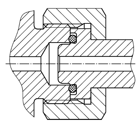
A filling plant is experiencing some issues when mounting fill adapters on the cylinder valves, see illustration image below.

Simply stated: The valve is supplied by another company; we supply the O-ring,connection piece and union nut.

The customer tightens the union nut with 4 Nm, at a rate of 100-800 rpm (automatic installation tool - customer built).
The problem is that approx. 1 in 5 union nuts tends to seize, and require around 20-30 Nm to loosen, requiring the need of a spanner to loosen again.(This happens immediately, no pressurization and/or product usage has been performed yet.) The interesting part is that the customer reports that after the first initial assembly; if one just handtighten the union nut a bit forcefully by hand (no tool, no 150-750 rpm) the nut still seizes and require a spanner to loosen again.

The valve is made of CW617B brass, the connection piece is made out of CW724R brass and the union nut is made out of CW614N brass. The thread in question is W21,80 x 1/14 per DIN 477.
The use of lubricant or anti-seize on the threads are forbidden due to regulations.

My first thought is galling of the threads, and/or other damage to the threads. I am visiting the customer next week and will be checking both the valve and the union nut, and wonder if there is something you guys think I should keep in mind? Anything to look out for in particular? It must be noted that this problem has just recently occured, so I will have to go through the process history and see what could have changed to make this problem appear in the first place.

Thank you for any input you may have.
Screenshot_2024-05-31_122537_gdedjp.png
 
Replies continue below

Recommended for you

There are oxygen safe lubricants, but that still leaves the fear of contamination.

The real problem remains - these connections are used millions of times each year and you have one customer that cannot seem to get the performance they want. It could be a worker has been messing around or the new machine is brutal or any of many other causes. Since they provided you no information other than that a wrench is involved there isn't much to speculate on as to the exact cause. For certain, using a wrench is the most common method to install and remove that nut, so it's not exceptional when they say they use one.

There are quick-connect, no turn options for high-throughput gas filling - but if you are in the business of making brass nuts, that probably isn't a solution you are looking for.

 
3DDave - Correct. And as you point out, all it takes is a worker that messes around. Which is why designing for oxygen service includes reducing the need for lubrication as much as possible.
I will find out more next week; if nothing else it should be an interesting exercise in "trust but verify".

"There are quick-connect, no turn options for high-throughput gas filling - but if you are in the business of making brass nuts, that probably isn't a solution you are looking for." They do exist yes. Most fill adapters I have seen of that type in Europe is in stainless steel, which is being phased out at a rapid speed. Great for 200 bar applications. One benefit of our connector is that it is approved for 360 bar oxygen service. The next step would be 690 bar for aerospace applications (I suppose), but that is outside my experience. Another downside of those high-throughput gas fillings is the (mostly) lack of swiveling functions and pricing - the industrial gas industry is cheap that way.
 
How much torque are you applying to this connection? It's sealed by an o-ring. Once the o-ring is compressed and the fitting faces contact additional torque contributes zero additional sealing. Consider reducing your torque.
 
TugboatEng: Original post: 4 Nm. The thread seizes and require 20-30 Nm to loosen. I suspect thread galling and will check further next week.
 
Good news - after it seizes a couple of times there will be plenty of thread clearance or it won't go on at all.

On your end - verify the material certifications to make sure the nuts are made of the alloy they are supposed to be made of. As a customer that would be the first question I'd have. The customer should already have gotten a thread gauge to check the nuts on delivery and should have checked post-seize, but you should also have the inspection record of that thread check in hand before you go.

It may also be worthwhile to have any stock in hand to be checked as well - suppliers can make mistakes. Suppliers can also lie. I've had cases where the material ordered was exactly what they had in stock, because no matter what was ordered they used the same material whether it was a match or not. The better ones will list in-stock what you want, then take the order, then tell you they don't actually have that, but do have something like it. The worse ones will expect you to figure it out. Sigh. (Yes, you, you retired a while ago, but when I put 7075 on the drawing I did not mean 6061 because you happened to have it. It should not take the anodize shop to call and say, hey that's some screwy 7075 you have here. Also, no, it was not a part subject to cyclic loading. It was a thin part that soldiers might want to use as a step stool and 6061 was marginal vs. the combat boot.)
 
The seizing may not be in the threads. There is also a bearing area between the nut and the tube end.
 
3DDave - All good points and I will do that. I have also reached out the the customer to see if they can to the same on their end with the valve manufacturer(s) - they are looking into it; to make sure the valve is indeed made out of the previously stated material/alloy. Correct, I have our internal thread check inspection record on hand and have requested that they redo the gauging on the seized valves and nuts (which they said they will do first thing tomorrow - interesting that they hadn't already but oh well.) It seems the customer also has valves from *7* different suppliers in their system currently in use, so now I have to see if there is a pattern there as well related to the seizing. We love a good process of elimination (where there is one that is) - especially when some of the valves are several decades old.

I have checked our internal inspection protocols after manufacturing, but also the inspection certificate on the raw material that we used. If something seems off after further testing then I will then put in a request for an alloy composition test - as you say the supplier can both be wrong or even worse; lie. I have unfortunately had experience with both, though not in existing suppliers.

TugboatEng - correct and I will check that out as well. Hopefully I will be able to fully cut through both a seizing and non-seizing valve/union nut pairs and check both the threads and the bearing area properly.
 
Hi Prometheus21

I am not sure what the torque wrench your customer is using however here is a motorised torque wrench which I found by Googling , it’s interesting to note the final torque figure should be achieved by hand. Have you run any calculations to estimate the stress in the threads? It might be worth doing that and comparing it with allowable stresses.

“Do not worry about your problems with mathematics, I assure you mine are far greater.” Albert Einstein
 
Desertfox - Hi again, I have seen those before, but I never knew the final torque figure should be achieved by hand to avoid over-torquing!

"Have you run any calculations to estimate the stress in the threads? It might be worth doing that and comparing it with allowable stresses." - I tried at one point, before the Senior engineer I studied under kindly reminded me that the stress in reality would be very different than on paper due to the Whitworth profile of the thread, and since slowly opening the cylinder valve is a very different load scenario than the more realistic shock load the threads experience when rapidly opening the valve. Before he passed away he did practical tests and had fun trying to find the "optimal" torque values (he was trying to find simple day-to-day torque values that could easily be used by any and all technicians in the field since "it's the easiest way to avoid the operators destroying the product - and then he laughed". He knew torque was an inaccurate method, but as he said; people had been using torque for decades when installing fittings. With a proper torque value he had yet to see anyone mess up the product using his recommended values; even with a +- 25% deviation.

That being said he recommended the following torque for the W21,80 x 1/14 thread, depending on the application, and they have worked since the 70s with no issues, accidents or tear-outs; (CW614N brass, stress relieved, factor of ignorance/safety=4 (before breaking - Tensile strength typically between 360-500 MPa).

1. Hand-tight to 5 Nm max (O-ring seal) where the product is often assembled and disassembled. More might be needed in environments subjected to moderate vibrations.
2. 15-30 Nm max (bull-nose and similar metal-to-metal designs) where the product is often assembled and disassembled.
3. 60-80 Nm max (gasket/metal seal) where the product is assembled once every 10 years. At that point the entire thing would be switched out.

That being said I have often wondered if I shouldn't pick up the calculations, if nothing else because its an interesting topic. I remember having read the work of the late Gerhard Friedrich Dose and it would be interesting to calculate and test strip-off diameter, shear values and the like.
Back in the day I remember being stumped by the nominal stress area in the Whitworth profile due to its rounded peaks and the 55° thread angle. Even in "Introduction to the Design and Behavior of Bolted Joints" - John H. Bickford, Michael Oliver; it is stated that "Different equations must be used for 55° Whitworth, Acme, Buttress, or other thread forms.". I can't remember ever having seen any stress area equations for those threads even being a topic in any literature that I have read so far.

And so endeth the ramble
 
Hi Prometheus21

Well I can’t argue against stuff that’s been working for 50 years👍.

However the failures you say are happening are on assembly and not in service, so my thoughts are to check the bearings stresses on the ends of the tube and nut and the shear stresses likely present on preloading the thread and whilst they are on,y estimates these stresses are mostly dependant on the major diameters of the fittings, the link gives formulas for the stress areas I am talking about and doesn’t directly mention the thread angle.WhilstI agree thread forms will play a part I think that’s taken care of in the thread data relating to calculating the said stress areas.


“Do not worry about your problems with mathematics, I assure you mine are far greater.” Albert Einstein
 
Prometheous

Does the female coupling have a hex on the outside diameter. The issue is oxygen compatible metals.
Maybe you should go to the floor, and have a tech show you how they assemble them. Record the procedure. And make sure it is not been over torqued or mis assemble incorrectly.
Maybe it's a procedure problem. Supprizenly
When their s an issue personnel attention. the problem go away.because of a physical audit, viewing helps a lot. How long have these parts being manufactured. Verify the threads with go and no go gages. Are the threads manufactured correctly. May be the threads are out of spec. And be to tight. Causing binding. Make fish chart and eliminate all possibilities.

Excuse the typing my cell phone is pain.
 
desertfox - thank you for the input and the document; I am looking into it.

mfgenggear - It does have a hex; and yes - potential metals to use is very limited due to the need for oxygen compatibility.
My initial impression after visiting the plant is that it is a fault with the torque tool used for assembly. I will be checking on a another fill plant that uses the same product to check how they install our product (they report no problems). I will then compare the two procedures as well as checking differences in valves, materials, assembly tool specs, threads ect. And yes, phone typing is painful, I'm just happy the classic keypad that assigned multiple letters to each number key is gone.

 
Pro
it is well known techs have a tendency to over torque with electric and air torque wrenches.
in case like this beam style torque wrench should be used inch lbs, these style very rarely go out of
calibration.
 
If you’re going to do stress calculations, to determine results due to high torque loading, I do suggest looking into the use of the kowalski formula, or something based on cylinder radial loading / deflection. Radial deflection may be an issue under high loading?
 
I believe to solve this issue is to hand install, ratchet tighten, then hand torque
It really can help. If there is a lox compatible
Lubricant will prevent seizing.

I worked on the atlas and centaur lox fuel iine both builds and assembly had special procedures for LOX assembly procedures.
 
Status
Not open for further replies.

Part and Inventory Search

Sponsor