Continue to Site

Eng-Tips is the largest engineering community on the Internet

Intelligent Work Forums for Engineering Professionals

  • Congratulations MintJulep on being selected by the Eng-Tips community for having the most helpful posts in the forums last week. Way to Go!

SEL 587 and Transformer Differential 5

Status
Not open for further replies.

Buckeye46

Electrical
Jun 23, 2018
20
A little too eager to wait until Monday when the protection engineers get back to work so I figured I would see what this forum knows about an issue we had on Friday with a 230/60kV transformer. It is brand new, has been in service for over two weeks through high and low load. Friday the generation plant that's off of this substation opens a remote breaker that forces all load to go into my substation and thru parallel banks, one of them being the one in question. As soon as that occurred, the SEL 587 tripped on an 87A. I am attaching images of the event reports. They don't make any sense. I could type an essay in here but I guess I will see if anything jumps out to you guys as to why this occurred. The primary CT waveform does look like its almost clipping.. but CT saturation shouldn't be an issue since it wasn't near its rated capacity by any means. Nor was it fault level current. The restraint and operate currents are pegged at 0.5 which makes no sense to me. Any ideas?
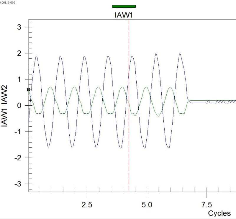
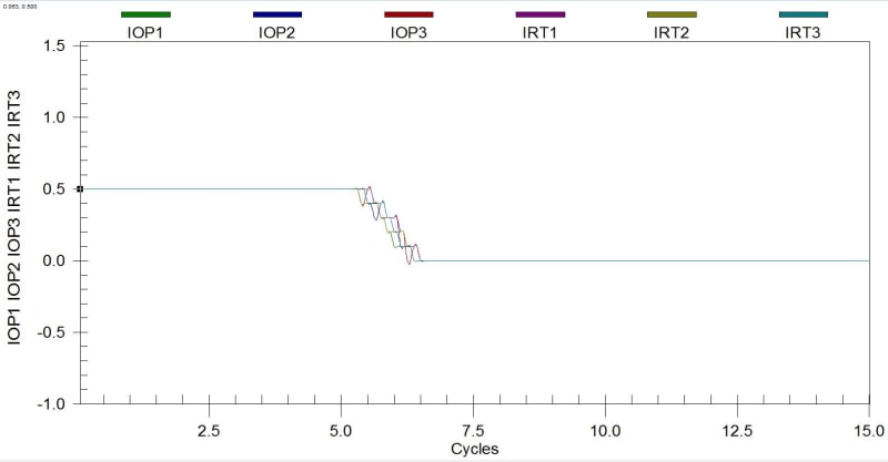
Capture_fhyehr.jpg


Capture2_qgvhlp.jpg
 
Replies continue below

Recommended for you

Do commissioning testing! The new relays make it so easy, and there are so many ways to mess up on transformer relaying. Parallel the new installation into an existing system, so if tripping occurs no outage occurs. Look for winding to winding current phasors that are 180 degrees out plus or minus 30 degrees depending on the delta-wye shift. Each winding should have phasors that are roughly equal in magnitude and separated by 120 degrees. Operating current should be close to zero, and restraint current should be equal to load. If using restricted earth fault, see that 3I0 or IG is equal to IN and 180 degrees out of phase. If using negative sequence overcurrent, see that 3I2 is small compared to load.
 
That's where i messed up. After a long day of switching we put the bank in service at around 8 pm. Once energized we were running around tracking down a few other issues and the bank never tripped offline. Pulled event reports from all of the relays from both banks and somehow missed the 587 differential report. I did review the currents during low load and saw no issue, assuming the phase rotation was supposed to be matching the bank. I am used to at least calculating the operate/restraint ratio to ensure it is within SEL's 0.1 standard. Just one of those times where everything was going wrong on the project and once its in service a little too much false relief. Just got back from resolving the issue today. Protection engineers didn't want to change the settings since that's how they have always configured transformer differentials. Somehow they missed that the design engineers had it H1(A) H2(C) H3(B) into the relay when they were expecting H1(A) H3(B) H2(C). Whatever. As a field guy the 3-line is the bible 99.9% of the time, they should of reviewed it closer. There was over 20 relays that were new or required setting changes at the sub or remote subs and we were given a month to do this start to finish along with bringing a new line in. Just glad its over haha
 
No need to trigger and pull event reports, just use the HMI built into AcSelerator Quickset or use a terminal window:

Level 1
=>met dif

XFMR 1 Date: 06/25/18 Time: 15:16:30.392


Operating Qty Restraint Qty
IOP1 IOP2 IOP3 IRT1 IRT2 IRT3
I (A,sec) 0.03 0.02 0.03 0.74 0.71 0.78

Second Harmonic Fifth Harmonic
Harmonic I1F2 I2F2 I3F2 I1F5 I2F5 I3F5
Current (A,sec) 0.01 0.01 0.03 0.02 0.03 0.03


Even quicker would just be to use the meter on the front panel but then that's just making me look worse [sad]
 
Status
Not open for further replies.

Part and Inventory Search

Sponsor