Continue to Site

Eng-Tips is the largest engineering community on the Internet

Intelligent Work Forums for Engineering Professionals

  • Congratulations KootK on being selected by the Eng-Tips community for having the most helpful posts in the forums last week. Way to Go!

Self Contained Sluice Gate - Actuator Stall Load 4

Status
Not open for further replies.

JoelTXCive

Civil/Environmental
Jul 24, 2016
921
I'm designing the anchor bolts for a self contained sluice gate with a motor controlled actuator.

These are 10x10 gates that have a self weight around 20 kips. The stall load of the 7.5hp motor is 300 kips due to all the mechanical advantage of the actuator's gearbox.

I have the tension/compression loads due to water pressure worked out, but have a question regarding how the gate load is transferred to the supporting structure.

This morning, a mechanical engineer told me the self contained gate sends no load to the supporting structure other than self weight.

I agree with this statement for normal operations; but not for a 'stuck gate' scenario.

Normal Operation
Under normal operation, the self weight of the gate is carried by the anchor bolts in shear. When the motor turns on the stem is in tension and the yoke beam receives a point load. Neglecting friction, the net load to the anchor bolts does not change.

'Stuck Gate' Situation
If the gate gets hung up; then the motor will continue to pull until it reaches the stall load.
Assuming nothing breaks in the gate; the full stall load (300 kips) will get sent to the anchor bolts.
In my mind, the gate frame will attempt to close up like a clam shell in this condition. The full 300 kips will be carried in shear by the anchor bolts.

Question (or Confirmation of my logic)
Do I need to design the anchor bolts to handle the full stall load of the motor?
Or, is my logic wrong; and no load gets sent to the structure?
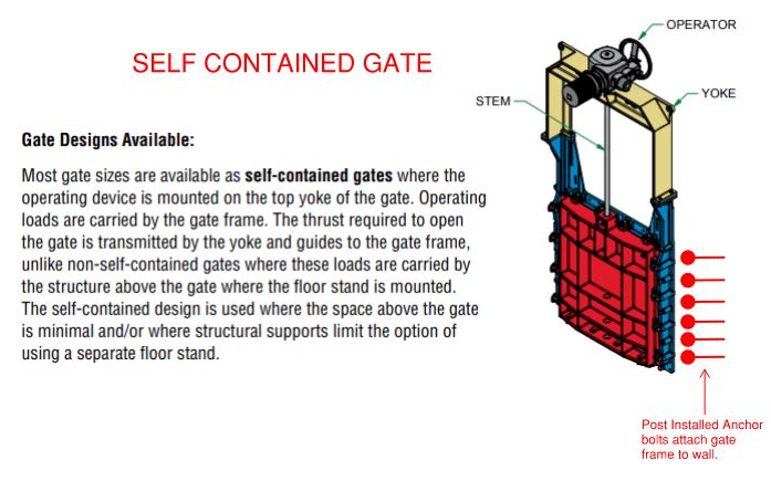
Sluice_Gate_Diagram_uo10cd.jpg


Thank you in advance.
 
Replies continue below

Recommended for you

GC_Hopi - The gates have what I call a 'double stem'.

There is an inner stainless steel stem that is a tension element. As the actuator motor turns, it "screws the gate upwards". The load is turned 180-degrees in the motor and is sent down the outer stem casing, which is a compression element.

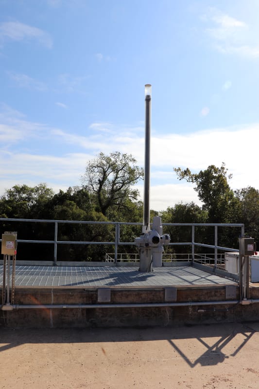
Below is a photo taken from the top after the permanent steel platforms were built. You can see the threaded tension stem inside the plastic raincover. At the base of the actuator you can see the much fatter compression portion of the stem.

No gate load goes to the steel platform at the top. The platform only carries the live human load.

North_Pump_Station_20_xermyl.jpg
 
Cool so the bracing would be important. The outer stem casing is easy to brace from the photo but the stem is tricker. They must splice the outer stem casing with flanges then insert stem guides. Gotta keep that Kl/r ratio down for the stem.
 
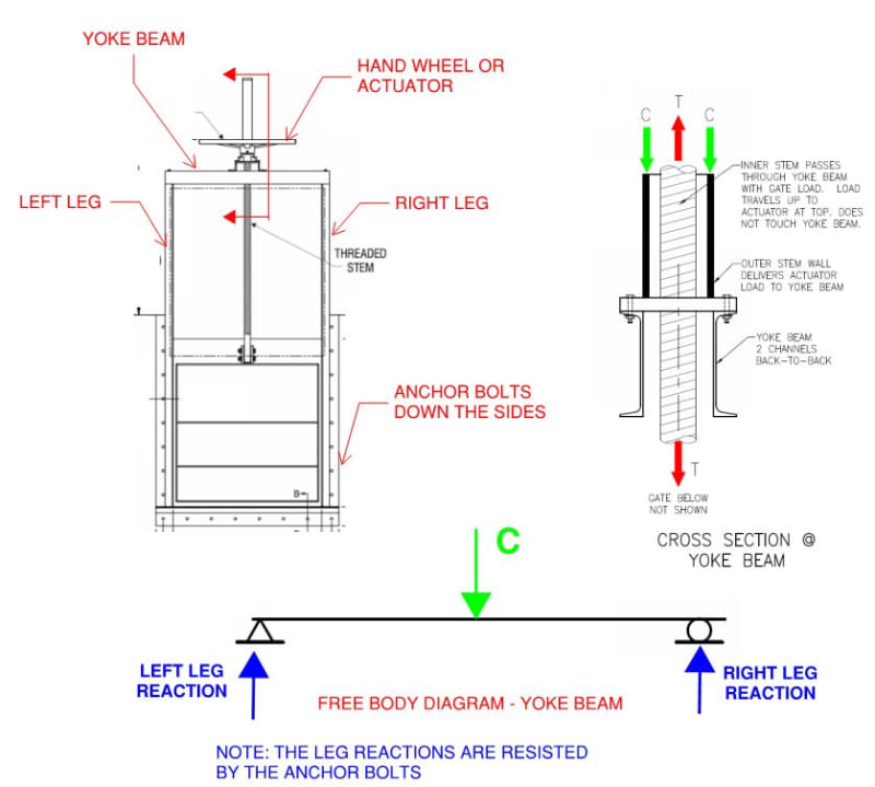
I'm coming around to Pham's line of thinking; where no stall load hits the anchor bolts (EDIT: INCORRECT). Below are my free body diagram and section cut.

capture_tonkcc.jpg


I have reviewed the gate manufacturer's design calcs; and both the inner and outer stems can handle the 300 kip stall load.

The yoke beam is loaded via the outer stem, since the inner stem does not touch it.

Does everyone agree with these two statements:

1) As load travels down the outer stem, it lands on the yoke beam, which is supported by the left and right legs. Any load that makes it into the legs is then carried by the side anchor bolts. This is normal operating condition. The anchor bolts only carry the self weight of the gate.

2) In a 'gate stuck' while opening situation, the gate becomes stuck and the gate motor keeps pulling. The inner stem load near instantly increases to the full stall load of the motor (300kips). Since the inner stem can handle this load and the gate doesn't move; the motor stalls. Once stalled; the motor sends NO load down the outer stem to the yoke beam. (EDIT: That statement is incorrect- see further discussion) This happens near instantaneously. Perhaps the yoke beam sees a nanosecond of this load as the motor fails.

What do you think?
 
In the "gate stuck" scenario, you have an internal force within the sluice gate system acting equal and opposite to the tension from the motor. The framing of the sluice gate structure will experience increased forces, but the anchors still only see the net weight of the system.
 
1) I'd add the frame load to that, too, but otherwise I agree.
2) I agree. For an application of this size, the motor is most likely a 3-phase induction motor. If the rotor stops spinning, the CEMF in the stator drops to zero and amperage tends (very quickly) toward infinity - or more likely the instantaneous trip set point on the breaker. Now this would only happen if you went from running smooth to jamming quickly. You're more likely to get a minor bind that bogs the motor but allows some movement I'd think. That will give you an increased load in your yoke that could be significantly higher than the normal operating load and last much longer than your nanoseconds. That said, I still don't think your anchors will see it.
 
If the gate is binding against the legs, the pull of the stem is balanced by the frictional force in the legs. In that case, the legs are effectively prestressed and carry the full binding force in axial compression. None of the binding force is transferred to the anchors.

If an unusual load, such as a log jam, were to cause added tension in the stem, it would add to the weight of the gate and the combined force would be resisted by the anchors.


BA
 
I mostly agree with sbisteel.
However, the steel frame flexes similar to a moment frame (bulging / squeezing), particularly at large moment demands. That is, the frame does not remain a perfect rectangle.
If the gate was flat or the equivalent of a floating log splitter, no problem, no transfer to the superstructure; reactions fully internally resolved.
But the concrete anchors do not permit free frame deflections, but instead add constraints (boundary conditions) to the system.
So most of the jamb loading is internal, but there are secondary loads transferred thru the anchors into the concrete due to deflections. The stiffer your steel gate frame is, the lower the secondary reactions are to your concrete anchors.
 
SBI, Pham, BA & ATSE:

I am in agreement with all of ya'll.

I have oscillated on this, but I should have trusted my initial gut feeling that depending on the obstruction type; a significant load could be passed to the anchors.

Summary is this:
[ul]
[li]Normal healthy operations result in self weight passed to anchors[/li]
[li]Gate binding type scenario - some load could be sent to anchors, but not 100% because we will get help from the frame and other factors.[/li]
[li]Tree Lodged in Gate - As the motor ramps up, additional load will be sent up the stem and back down to the yoke beam. This load will be carried by the anchors.[/li]
[/ul]

Currently, I can get ~265 kips shear (applied concurrently with the full unseating head pressure) out of my 40 bolt anchor setup. The full internal stall load is 300 kips. I might be able to squeak another anchor or two in, but I'm at the point of diminishing returns and approaching potential group effects on the anchors.

I'm going to talk with the project manager about it. There are torque reducers on the actuators that we can set, but they can be manually over-ridden in the field. I know there is a concern that an operator could over-ride the safety mechanisms and damage the gate or anchors. We might also talk with the electrical engineers about reducing the actuator size.


I could see that if the tree is supported by something other than the bottom of the gate frame. Something tells me, though, that the the tree would be guillotined before the anchors failed.
 
phamENG said:
I could see that if the tree is supported by something other than the bottom of the gate frame. Something tells me, though, that the the tree would be guillotined before the anchors failed.

Perhaps, but the force required to shear the tree would need to be resisted by the anchors. If the tree was eccentric to the stem, it could cause rotation to the gate which might initiate binding.

The probability of trees or logs floating into the gate may be sufficiently low that it need not be considered in design.


BA
 
The chances of trees or logs get into the gate are very slim as a trash rack should be constructed in front of the gate.
 
Status
Not open for further replies.

Part and Inventory Search

Sponsor