Continue to Site

Eng-Tips is the largest engineering community on the Internet

Intelligent Work Forums for Engineering Professionals

  • Congratulations KootK on being selected by the Eng-Tips community for having the most helpful posts in the forums last week. Way to Go!

Sentry pulsation Dampener on suction and Discharge location

Status
Not open for further replies.

bmw318be

Mechanical
Jun 16, 2010
197
Hi i read about sentry pulsation dampener and inlet stabilizer.


I would like to know if the suction and discharge dampener can be installed in this configuration.

Quote
LOCATION: Location is important because of wave frequency and fluid dynamics. Location directly effects dampened

performance. The pulsation dampener should be installed as close as possible to the pump discharge and no further away than 10 pipe diameters. Installation should be on a tee in the fluid flow path. Do not install the
dampener on a branch or riser. The farther away the dampener inlet is from the pump discharge, the less effective the unit will be.

A dampener installed on a riser or dead-end leg of pipe can actually increase pulsation. A pulse traveling towarc the dampener has another pulse directly behind it. When the first pulse is reversed after contact with the dampener, it crashes into the next pulse disrupting the entire wave sequence. This action can change the system fluid harmonics, which may lead to increased pulsation.


(End)

What is the riser or dead end referring ?

4 Types of Installations
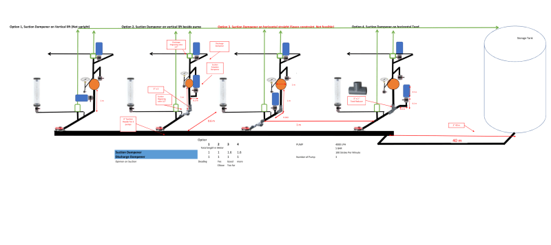
4_Alternative_installation_uu0jqv.png
 
Replies continue below

Recommended for you

i believe it would be end of piping without any connection or equipment.
 
Your option #3 is the best piping arrangement.

[link bmw318be (Mechanical) ]The pulsation dampener should be installed as close as possible to the pump discharge and further away than 10 pipe diameters.[/url]

You left out the word "no". The pulsation dampener should be installed as close as possible to the pump discharge and no further away than 10 pipe diameters.

Position a dampening system on the suction line as close as possible to the pump; this reduces pulsations and the associated inertia effects and therefore reduces total friction loss

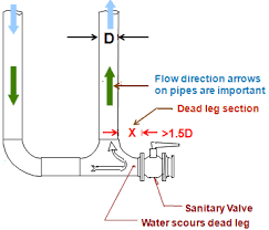
So, what qualifies as a dead-leg? Piping segments continuously exposed to the process but without normal flow or provision for flow, including lines closed by flanges, welded caps or other fittings, nearly always are considered dead-legs. However, other situations are trickier to classify. Two particular issues that perplex the most are dealing with intermittent flow lines and defining how much line is required for something to be classified as a dead-leg.

"Piping schematic showing Dead Leg"

untitled_gynixg.png
 
Hi Bimr,
Thanks for your illustration, is the dead leg create more pulsation and hoe this couod be favourable in the hydraukic metering pump dampener installation.


Is option 2 and 4 is considered a dead leg as there would be one way flow and return due to dead leg.

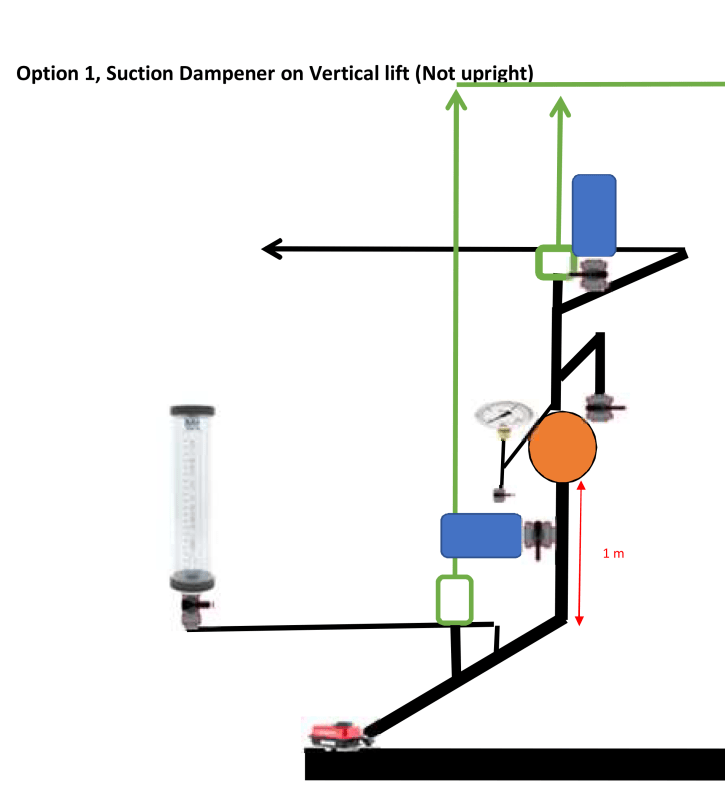
I was advised by manufacturer for suction dampener that installation 1 is dead leg and some other manufacturer considered installation 1 is the closest to the pump and favourable.

Any opinion on the schemantic attached
 
Yes, options #2 and #4 may be considered deadlegs. #4 is definitely more of a deadleg than #2.

The schematic in your post doesn't show schematic #1.
 
Dear Bimr,

Thanks for your input, I added the illustration of

Schematic 1 (I believe this not recommended)
Option_1_cosjlc.png


May I know the impact on dead leg on the metering pump:

1. Sediments
2. Unbalance flow

Any others that you could possibly think of

I learnt to better understand in the youtube experiment, i appreciate after watching you could help to give your opinion in term of Hydraulic pump principle as it accelerate and decelerate and the suction dampener would help to stabilize. How this can impact the dead leg.


Principle of Suction & Discharge dampener

Horizontal deadleg

Vertical downward deadleg pipe

Appreciate your comment and inputs
 
I would not expect that either suction or discharge dampers (type as shown) would have any affect on debris collecting or removal in dead-leg pipes, since they are not in the flow stream. Dead-leg location and length can affect pipe acoustics (pulsations), but that topic is beyond this discussion.

Walt
 
There is not much difference between #1 and #3 schematic and I would not expect much difference in actual operation.

I don't expect that either suction or discharge dampers would have any affect on debris collecting or removal in dead-leg pipes. In addition, for your application, the amount of sediment will be nil.

I would not expect any unbalanced flow either.

Your system is relatively small. With large systems and high flows, it is more important to address the issues that you are bringing up. With smaller systems, the effects are less important and may be ignored.

If you follow the general design guidelines put out by the manufacturers, you should not have any problems. The problems occur when people read the directions after they have everything is installed.
 
Dear Bimr,

The pipe is a PVC pipe, pumping a water with small concentration of chlorine 1%, may I get your opinion on another possible option 5 as Option 3 is not feasible due to space constraint and maintainability of the pump head. Therefore, I would like to consider a straight elbow of 10 pipe diameter 2" and straight elbow back to the suction header of 6"

Link


The option #5 schematic would be an acceptable design.
 
Status
Not open for further replies.

Part and Inventory Search

Sponsor