Eng-Tips is the largest engineering community on the Internet

Intelligent Work Forums for Engineering Professionals

Set point of pressure switch 1

Status
Not open for further replies.

Zuma10000

Industrial
Mar 2, 2024
5
0
0
SA
Hello,

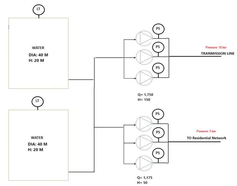
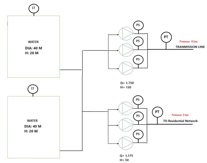
Is there any rule or standard to define the set point of pressure switch after pump for protection purpose ?
 
Replies continue below

Recommended for you

Pressure switch high or low?

Low should be set at a pressure where you stay inside the pump curve.

High set at or below design pressure of the connected system.

Remember - More details = better answers
Also: If you get a response it's polite to respond to it.
 
Thank you MortenA

Thank you so much Littleinch, it is a high pressure, what you mean by connected system?,
ADo you mean design pipe pressure because it is a discharge pump from storage water tank used for water distribution.
 
Yes the design pressure of the piping system downstream from your pump.

What other purpose does it serve?

Remember - More details = better answers
Also: If you get a response it's polite to respond to it.
 
The pump is used only for water distribution but the water will go pass first on surge vessel then water go to network.
Now the consultant is asking about documented paper or standard state how to calculate the value of pressure switch
 
Fire the consultant as they clearly don't know what they are doing and hire one who does....

Remember - More details = better answers
Also: If you get a response it's polite to respond to it.
 
@littleinch,

Thats more or less common sense. But a standard? I agree wrt to the consultant mentioned.


--- Best regards, Morten Andersen
 
You will have to tell us more.
Show us a process sketch which shows how this pump is controlled, including details on min flow recycle, if any.
Performance curve for this pump (Q-h curve). Max normal level in the feed storage tank ?
What is in this "surge tank " ? Design pressure of this tank ?
Max recommended operating pressure of the distribution piping and that for the pump discharge piping also
Water distribution to where ? Residential, industrial ? What is normal max delivery pressure to these users ?
 
Dear @georgeverghese

Thank you for your reply, I attached the sketch
and here is the reply
Show us a process sketch which shows how this pump is controlled:
Pump use VFD.
Level Transmitter and Pressure switch signals used to stop the Pump.


Max normal level in the feed storage tank:
18 meters

What is in this "surge tank" ? Design pressure of this tank?
Sorry no surge tank

Max recommended operating pressure of the distribution piping and that for the pump discharge piping also
Pump will work on head pressure, 15 bar and 5 bar

Water distribution to where? Transmission and Residential

What is normal max delivery pressure to these users? Pump pressure


psTE_sfhxax.jpg
 
So the VFDs' on each of these 2 systems is operated by a dedicated master pressure controller sitting some where on pump discharge ? Presumably residential master PIC is set at 5barg, while master PIC for transmission line is set at 15barg. And the VFD on each pump may be operating on one of 3 speed ranges reset by PIC output ?

Are you sure these pressure switches are meant for safety overpressure protection ? Or are they in dual service as process control devices cutting out relevant pump as line pressure increases during low flow demand ? If this latter is the case, then
[And the VFD on each pump may be operating on one of 3 speed ranges reset by PIC output ?] wont be necessary

Which is it ? Has some one prepared the process control narratives for these 2 systems, where you will find the answers to these.


Pressure switch is working for safety overpressure protection only, because there is PT on the main line to adjust the VFD (attach new schematic)

VFD is adjusted to work on 4.5 bar.

I was going to use API 610 and set the pressure switch on the shut-off pressure of the pump or little bit, what is your opinion ?

psTE_x6up1a.jpg
 
Okay, so these are to protect the pump in case of blocked in flow potentially going up to dead head operation.
Since you have a variable suction static suction head ( head in feed tank varying up to 18m), would suggest using a differential pressure switch dPSH ( dP between pump suction and pump discharge ) rather than discharge pressure switch. Set the dP to that equivalent to the head developed at min flow for each of these 2 sets of pumps.

So for the transmission set, if head developed at min flow is say 170m at max normal speed, then set the dPSH at 17bar. This assumes that in the worst case, when pump discharge pressure = 17 + 1.8 = 18.8barg, that piping design pressure can still handle this pressure. Check the Q-h curve for this pump set to see what the head is at min flow at max normal speed.
In this case, you also need to check that water hammer pressure does not exceed 1.1x to 1.3x piping design pressure, if water hammer can occur.

For the residential set, use the same approach.
 
Zuma,

You're answering your own question here.

If VFD for the 5 bar system is set at 4.5 bar, then set your pressure trip to 5 bar ( or if you want to be a bit cautious to avoid spurious trips set it to 5.5 or 6 bar)

I assume therefore you set the higher pressure VFD control to 14 bar?
Then set your pressure trip to 15 or 16 bar.

Why is the system set to 5 bar and 15 bar? Find out that and all will become clearer. e.g. are there any relief valves anywhere? What is the lowest actual pressure rating of anything in the downstream system?

Either way I would also add into the shutdown circuit a timer function to reduce the potential for spurious trips caused by a sudden spike in pressure.

A time period of 5 or 10 seconds should be enough to smooth out any transient pressure spikes as when the pumps come on and off line or ramp up from the VFD control and overshoot a little bit.

If you don't the operators will either tweak the setting higher or disconnect it...

Remember - More details = better answers
Also: If you get a response it's polite to respond to it.
 
For both pump sets, add PSH on pump discharge also. dPSH setting is not fixed, it should be speed compensated.

For transmission line pump set, what is the max permissible operating pressure of this piping system (MOP) for the material and pipe class you've got. Set PSH at 90 % of this value, and also add a PSV at MAWP if pump deadhead pressure with tank at 18m can exceed MAWP.

For residential pump set, setting the PSH at 90 % of MOP may be too high. Say 7-8barg. Pump set may be incapable of breaching the MAWP of the piping system, so PSV not required.
 
Status
Not open for further replies.
Back
Top