Continue to Site

Eng-Tips is the largest engineering community on the Internet

Intelligent Work Forums for Engineering Professionals

  • Congratulations GregLocock on being selected by the Eng-Tips community for having the most helpful posts in the forums last week. Way to Go!

Shaft alignment sensor mounting

Status
Not open for further replies.
Aug 30, 2012
200
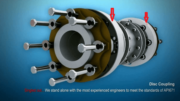
Is it possible to mount the shaft alignment sensor on the flexible hub (but in locked position) ?Will it affect the readings?

Is it possible to mount the shaft alignment sensor on the taper shaft ?Will it affect the readings?

 
Replies continue below

Recommended for you

coupling_i4goa3.png
 
I would say no, unless you could verify the blocks rendered rigidity in the flexible joints. Are you sure that the flanges with arrow markers are not a rigid part of the shaft hubs? Can you show a cut-away drawing?

Walt
 
We have this style of coupling in a few of our larger centrifugal compressors. We have mounted the lasers to the shrouds, as you proposed, with the center spacer removed and the shipping screws locked in place to prevent flexing. You have to be very careful, but this can be done. On others, we have used a stud threaded into a hole in the center of the shaft to mount the laser on one or both sides. You can mount the laser on the tapered shaft end with the hubs removed, but this is a lot of extra work to remove and reinstall the hubs. I would usually prefer the first method I described. Mounting to the taper would concern me about any damage to the hub contact area.

I don't care for this coupling design because of this problem and the fact that it is nearly impossible to get direct heat onto the hub for removal.

Capture_irgffp.jpg


Johnny Pellin
 
Concern is if the hub is not locked squarely (slightly angled) , would it affect the reading ?
 
No, it would not. It is only important that it does not flex while you are taking readings.

Johnny Pellin
 
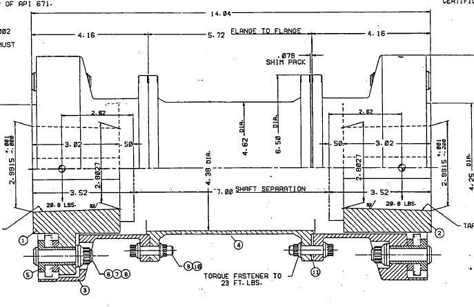
I would mount laser brackets with magnets or adhesive onto rigid hub faces labeled 1 and 2 in drawing. I would not try to make coupling rigid for alignment measurements. You should be able to mount laser bracket on a tapered shaft. If you cannot adjust laser heads enough to compensate for the taper angle, then place some small shims under the bracket V-blocks to remove most of the taper angle; just keep mounting brackets rigid to shafts.

Walt
 
Hi Strong, we use the shaft ends to mount an adapter to rotate the shaft.
The magnet cannot be on that spot.
 
You can't use a strap wrench around spool piece or socket wrench on bolts to rotate shaft?

Walt
 
The strap could slip.
We dont touch the bolts on the disc pack.
The bolt on the spacer is about 3/8'', too small,might shear.
 
I give - how could bolts that can take the full torque transmitted between the shafts under full power be sheared by applying torque at essentially zero power and what difference does it make if the strap has some slippage?
 
The slippage does not allow the strap to grip.

The shaft is being rotated by a set of bolts in normal condition. If a socket is installed on one bolt to rotate the shaft, it could overload it.
 
How much torque is required and how large is the shaft?
 
Shaft dia. About 160mm.
RAted torque 120 000 Nm
Driver rated power about 38 MW

Correction.
Bolt/nut size at position 9 , 10 is 5/8 , material alloy steel.

 
About how much torque does it take to rotate the shaft (s) during alignment?
Is the spool piece left in place during alignment ?

My olde German strap wrench with a reinforced plastic strap gets an EXCELLENT grip on a clean metal surface.
Looks like this -

I envision Heavier duty strap wrenches with a tough fabric strap might benefit from traction enhancing modifications.
- Spraying the working face of the shaft with thin coat of a product like plasti-dip, flex seal, etc first proven to have good friction characteristics.
- a Strip of fine sandpaper made by gluing two narrow strips back to back, abrasive side out wrapped around the shaft.
- a strip of rubber with good friction characteristics wrapped around the shaft.


The main problem with rotating the shaft with a strap wrench is that the strap would have to be on the shroud or the center spacer. There is no place to mount the lasers other than the shroud. This requires that the center spacer must be removed. Otherwise, you would be checking alignment on a solid structure (perfect alignment every time). If the lasers are on the shrouds, I would not want to use the strap on the shrouds since any flex or movement relative to the shaft would invalidate the readings. Using the puller holes on the face of the hub with an adapter to rotate the shaft seems like a very good method.

Johnny Pellin
 
Very funny. How much torque does it take to turn the shaft? You know, the minimum torque to get it to turn?

The mounts for the lasers should be on the end parts that are locked to the shafts, not to the spacer that is attached by flex plates.

16 questions left.
 
Status
Not open for further replies.

Part and Inventory Search

Sponsor