Continue to Site

Eng-Tips is the largest engineering community on the Internet

Intelligent Work Forums for Engineering Professionals

  • Congratulations cowski on being selected by the Eng-Tips community for having the most helpful posts in the forums last week. Way to Go!

Shear Deformation - Point Moment 7

Status
Not open for further replies.

Celt83

Structural
Sep 4, 2007
2,083
This is probably something that is very easy and I am way overthinking it.

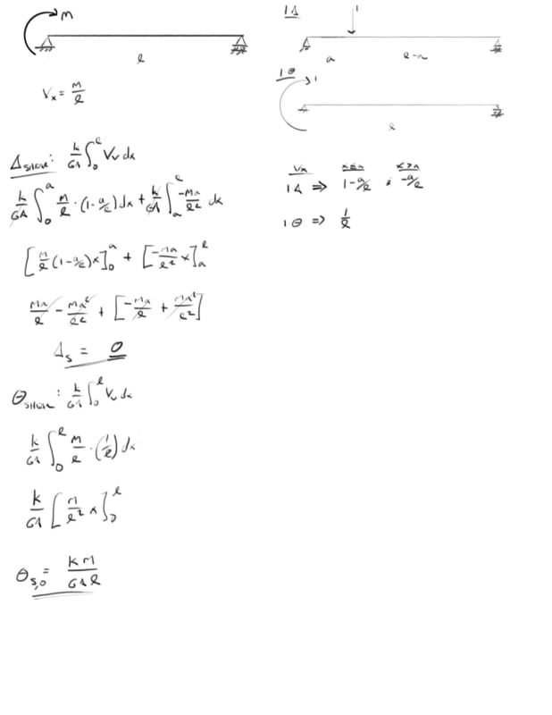
I've done the unit force method which shows that the shear deformation from a point moment is 0 at all locations on a simple span. I've done the same thing to show that the shear component of the slope at any location on the beam is constant = k M / A G L. Here is where I get hung up if the slope is constant and non-zero why is the deflection 0 from a math stand point, the mechanics make sense to me but I'm lost in the math on this one.

I have a great mechanics of materials book by Timoshenko and Young which for me so far has the best break down of shear deformations I've been able to find and in there they present that the slope due to shear is simply dy/dx = tau,max / G = k Vx / A G, which aligns with my unit method solution of k M / A G L.

integrating that once yields: y,shear = k M x / G A L + C1

Initial conditions are x=0, y=0 and x=L, y=0 the first condition yields C1 = 0, however the second condition yields C1 = k M / A G ... so I get that something is missing here which would should result in y,shear = 0 but I am at a loss.

would greatly appreciate any insight on this one.
2_e00mlq.jpg


Open Source Structural Applications:
 
Replies continue below

Recommended for you

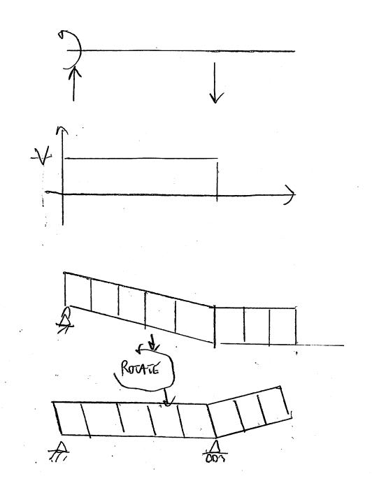
Celt83 - maybe the easiest way to look at it is to consider the simply supported case as a cantilever loading followed by a rotation to return the free end to its original position. The additional deflection at midspan is not due to shear deflection over a length with zero shear, it is due to additional rotation.

Doug Jenkins
Interactive Design Services
 
IDS said:
...since the slope is defined by the angle of vertical sections, not the slope of the bottom face (or centre line); see KootK's 3rd section.

I think I disagree with this statement all the text references I have specifically show that the slope is defined as the change in the vertical movement of the center line?

Excerpt from Elements of Strength of Materials 5th Edition, Timoshenko and Young:
20190422_105533_ngsqcx.jpg


Open Source Structural Applications:
 
Capture_udlwfb.png


Trying to combine KootK's sketch with the bending action of a small differential section of beam. Bending action should really show the bottom elongating and top shortening.

Edit: More I look at my sketch I don't like it, think the left edge would move further from vertical while the right edge would tend back towards vertical, accounting for the not drawn elongation and shortening of the bottom and top fibers due the bending action.

Open Source Structural Applications:
 
celt said:
I think I disagree with this statement all the text references I have specifically show that the slope is defined as the change in the vertical movement of the center line?

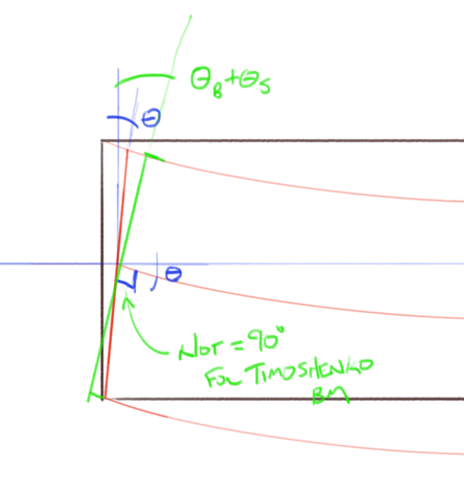
1) I scratched my head over this a fair bit too as I've never once seen an example in the literature where the vertical sides didn't remain vertical. I stand by the argument, however, and believe that the paucity of non-vertical shearing elements is just a function of a) the limited treatment of shear deflection in general in the literature b) the fact that, as I'll describe below, what you do get in the literature generally does not involve concentrated moments.

2) Another part that I struggled with is that, if one accepts the premise that non-vertical shearing elements are legitimate, how does the element "decide" what it's own orientation will be? As I'll illustrate in a subsequent post, we're already delving into a) Pure vertical deformation b) pure horizontal deformation and c) stuff in between those extremes.

3) I haven't fully sorted any of this out myself so please take what follow as discussion points rather than statements of fact.

4) I contend that there is something special about he load source that determines the nature of the shearing deformation. When the shearing is initiated by vertical load, the vertical faces of the element remain vertical (shear deformation only considered). When the shearing is initiated by horizontal load, the horizontal faces of the element remain horizontal. See the third sketch in my post above. I think that a concentrated moment resembles as horizontal force couple in some fashion which fundamentally changes the nature of the problem. In a way, it forces the problem to take on 2D characteristics in addition to 1D.

KootK said:
More specifically, you need a reversal of shear, not just a change in shear

IDS said:
is not correct.

Thanks for your comment IDS. I see what you're getting at and, very strictly speaking, I agree. When I made that statement I was thinking of "simple span" beams as being beams not subject to concentrate moments. Initially, I was thinking this way out of practicality. In the real world, a concentrated moment is almost always indicative of some kind of back-span/continuity. I now feel that this also has something to do with #4 above. A load such as a concentrated moment will change the character of the shearing deformation as described. So I would reformulate my statement as.

KootK said:
In particular, you do need a change in shear in order to have vertical shear deformation in a simple span member. More specifically, you need a reversal of shear, not just a change in shear.


5) For a simple span member not subjected to concentrated moments, or any other loading that would result in vertical shear planes not remaining vertical, a reversal of shear is required to ensure that shearing deformation is compatible with the boundary conditions.

I shall wait patiently to be proven wrong yet again...

 
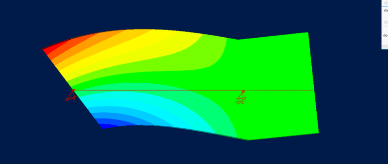
going back to your post on the 19th, with the FEA results,
so the FEM result (0.0084) is just about your analytical results kM/(GAL) = 4.18E-6*10000/5 = 0.00836 … yes?

what I find "odd" is that you're getting the same deflection from different slopes ??

another day in paradise, or is paradise one day closer ?
 
IDS said:
maybe the easiest way to look at it is to consider the simply supported case as a cantilever loading followed by a rotation to return the free end to its original position.

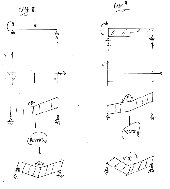
- This actually the superposition that I've been envisioning from the beginning.

- See the sketches below for the scenarios that have been proposed.

- There are some inaccuracies in my depictions of the strains. It's just taking too long to get it perfect.

- Case 4 is interesting. I think that you can have vertical shear deformation if you have a variable cross section.

c01_jug5xu.png


c02_f2qm7k.png
 
Celt83 said:
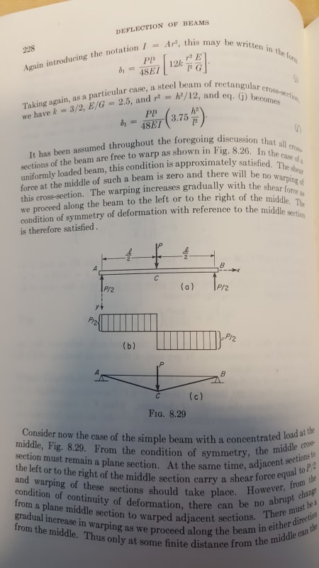
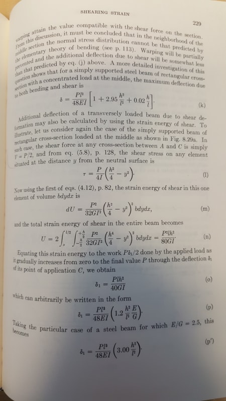
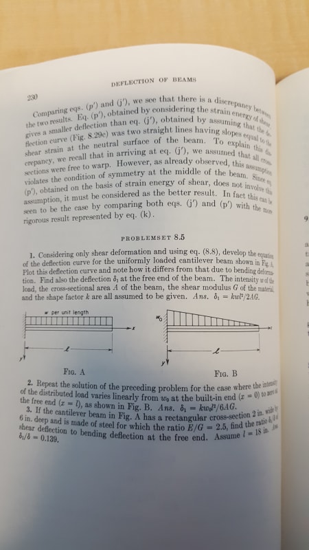
There is a section in the Timoshenko book that deals with a single point load which I think would be relevant the discussion,excerpt below:
(Hopefully these are legible)

I'm not sure what the concern is in this thread. Are we concerned about the difference between expressions j' and p' in the reference text? If so, we have to consider shear strain energy. Otherwise, a simpler solution is available.

BA
 
so instead of trying to look at some segment in the beam, I looked at the end for Euler-Bernoulli beams the cross section remains normal to the elastic curve but a Timoshenko beam does not have this restriction, both do have plain sections remaining plain.

So for bending if the cross section remains normal to the elastic curve measuring the angle horizontal or vertical won't matter you get that same result and the deflection is directly related to the cross section slope. Under shear deformation the cross section may not remain normal to the elastic curve and the rotation of the cross section is not directly linked to the deflection curve.

Capture_jkx5m0.png


Open Source Structural Applications:
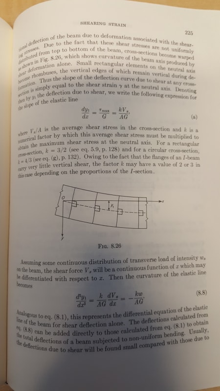
 
For a point load at midspan (or anywhere in the span) the conjugate beam method may be used with the imaginary loading diagram of M + kEIw/AG where w = dV/dx.

Recognizing the fact that an angle change occurs over a finite length of beam, we could say that w = P/h where h is the height of the beam. Or perhaps w = P/2h. The concentrated load P is deemed to be distributed over a length h or 2h for purposes of including shear deflection. Then use the conjugate beam method to determine deflection due to combined moment and shear.

BA
 
KootK said:
5) For a simple span member not subjected to concentrated moments, or any other loading that would result in vertical shear planes not remaining vertical, a reversal of shear is required to ensure that shearing deformation is compatible with the boundary conditions.

I cannot understand the intent of this comment. The example in the OP has no shear stress reversal, but the deformation is compatible with boundary conditions, namely zero shear deflection throughout the span.

A beam with a single point load will have a shear stress reversal at the load but a beam with several point loads will have shear stress reversal at one of the loads (assuming all loads are gravity loads) but the remainder will experience merely a change in shear stress, not a reversal.


BA
 
BAretired said:
I cannot understand the intent of this comment.

IDS brought to our attention a load case where a shear reversal was not a corollary to having vertical shear deflection in a simple span member. And that neutered the "rule" that I'd proposed. After noodling on it for a while, I came to the conclusion that the rule did hold so long as some oddball loading conditions were excluded. Those odd conditions were/are the ones mentioned in the statement that you quoted in your latest comment. So my intent was to refine my rule in order to adapt it to the inconsistency that IDS pointed out. I'd prefer not to spend too much time on the "rule" really as I don't think that it's terribly germane to the key ideas of this thread. I only mentioned it initially as a way to extend your rule about needing to have a step in the shear diagram to have vertical shear deflection.

BAretired said:
A beam with a single point load will have a shear stress reversal at the load but a beam with several point loads will have shear stress reversal at one of the loads (assuming all loads are gravity loads) but the remainder will experience merely a change in shear stress, not a reversal.

Agreed. The "rule" only requires a single shear reversal anywhere along the span which jives with your statement above.

 
Euler-Bernoulli beam theory doesn't account for deflection due to shear.

Timoshenko adds the effects of shear (generally small and negligible). Shear deflection depends on the change of rotation (of the plane section remaining plane) along the beam.

So in this "odd ball" example, the moment is M/L*x, so phi(x) = M/(2EIL)*x^2 + C, and dw/dx = M/(LkAG) - M/(2EIL)*x^2 - C
and w(x) = M/(LkAG)*x - M/(6EIL)*x^3 - Cx + K
K = 0, CL = M/(kAG) - M/(6EI)*L^2 … C = M/(LkAG) - M/(6EIL)*L^2

and this shows that the shear deflection terms cancel, and w(x) = M/(6EIL)*L^2*x - M/(6EIL)*x^3

another day in paradise, or is paradise one day closer ?
 
Celt83 said:
Direct substitution of the first boundary condition yields C1=0, However knowing y=0 at x=0 and x=L it is clear that the only real solution for C1 is that it equals -k*m*x / G*A*l. Sorry my calculus is a bit rusty.

Not as rusty as mine it seems. If I remember correctly, a constant of integration can't include a variable. My earlier post was wrong but cannot be edited at this late date.

If y1 is deflection due to shear, I can't understand how dy1/dx (the slope of the neutral axis) can have a value other than zero with moment M applied at one support.

BA
 
BA:
Yeah I think rb1957 has it, I think that the equation I'm trying to use from the text reference while not explicitly stating,or maybe they do but my lack of understanding didn't realize it, it is really intended only for vertically applied loads and even then really only gives the correct deflection for uniform loads.

rb1957's derivation uses the Timoshenko Beam equations: [URL unfurl="true"]https://en.wikipedia.org/wiki/Timoshenko_beam_theory[/url]


Open Source Structural Applications:
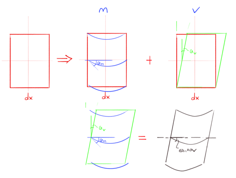
 
it's an odd conclusion, maybe due (as BA pointed out early on) that there are no shear loads applied to the beam.

I was thinking that since there was shear in the beam, then there should be shear deflections (small enough for us to ignore, in practice).

You have to be very careful using equations you don't (fully) understand. [bigsmile]

another day in paradise, or is paradise one day closer ?
 
Sorry to bring this topic back up but have hit another snag and the commercial software results aren't making sense to me.

Same loading point moment except this time the beam has a cantilever on one end. I was expecting the shear deflection in the cantilever to be 0 as well since we seem to have agreed that the slope was a measure of the vertical angle and not the tangent of the deflection curve. For bending deflection the cantilever deflection is simply length of the cantilever times the slope at the support for small angles. The commercial software is showing a full reversal of the cantilever deflection when shear effects are included which would equate to the the same slope*distance formula but the slope caused by shear in the case of a point moment is not a measure of the tangent of the deflection curve? or is it because the cantilever end is free the horizontal deformation of the beam top/bottom surfaces does allow for this reversal of deflection to occur, so slope*distance is still valid.

Bending delta:
Capture_gx16i3.png


Bending+Shear delta:
Capture_rq4ei2.png


Supports, Loading, and Section:
Capture_qfiozm.png


Full cross section deformation which aligns with KootK sketch showing the top/bottom surface deformations:
Capture_zfrwlc.png


EDIT:
slope*length, the slope is a measure of the normal of the cross section relative to an axis there is no load on the cantilever and no restraint to keep the end down so there is no other deformation and the deflection curve is perpendicular to cross section normal. This just happens to be another weird case.

Open Source Structural Applications:
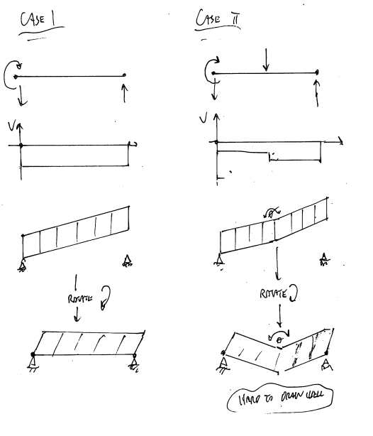
 
OP said:
slope*length, the slope is a measure of the normal of the cross section relative to an axis there is no load on the cantilever and no restraint to keep the end down so there is no other deformation and the deflection curve is perpendicular to cross section normal. This just happens to be another weird case.

Yup, beat me to it.

c01_v4yjmc.jpg
 
The part of this that has been nagging at me has been reconciling how the beam "knows" in any given situation whether or not shear strains should produce a vertical straining or a horizontal straining. As shown in my little sketches, I'm able to come up with an algorithm that accurately predicts what will happen based on enforcing compatibility between the boundary conditions and the anticipated shear strain. But predicting is not quite the same as knowing why.

I now have an energy based theory for why. Try this on for size, speaking only to shear deformation:

1) A load must do work that produces displacement at the load and in the sense of the load. A vertical point load on a beam must produce vertical shear displacement at the load etc.

2) When an end moment is applied to a beam, it can only do work if the the resulting shear strain at the end of the beam would produce a rotation at the end of the beam. And a shear strain can only produce a rotation at the beam end if the shearing strain results in horizontal relative displacement between the top and bottom of the beam. A vertical strain wouldn't result in end rotation of the beam.

3) 1 + 2 = a moment is always going to produce shear straining that results in horizontal straining.

The terms vertical straining and horizontal straining are too imprecise I think. The new, KootK law of shearing deformation should read as follows:

1) A transverse load will always produce a shear strain perpendicular to the axis of the member.

2) A torque load will always produce a shear strain parallel to the axis of the member.

I feel as though we should write a white paper on this now. You know, for the benefit of the six engineers on the planet that might care. It's been a fun thread for sure.

 
Status
Not open for further replies.

Part and Inventory Search

Sponsor