Continue to Site

Eng-Tips is the largest engineering community on the Internet

Intelligent Work Forums for Engineering Professionals

  • Congratulations cowski on being selected by the Eng-Tips community for having the most helpful posts in the forums last week. Way to Go!

Shear Deformation - Point Moment 7

Status
Not open for further replies.

Celt83

Structural
Sep 4, 2007
2,083
This is probably something that is very easy and I am way overthinking it.

I've done the unit force method which shows that the shear deformation from a point moment is 0 at all locations on a simple span. I've done the same thing to show that the shear component of the slope at any location on the beam is constant = k M / A G L. Here is where I get hung up if the slope is constant and non-zero why is the deflection 0 from a math stand point, the mechanics make sense to me but I'm lost in the math on this one.

I have a great mechanics of materials book by Timoshenko and Young which for me so far has the best break down of shear deformations I've been able to find and in there they present that the slope due to shear is simply dy/dx = tau,max / G = k Vx / A G, which aligns with my unit method solution of k M / A G L.

integrating that once yields: y,shear = k M x / G A L + C1

Initial conditions are x=0, y=0 and x=L, y=0 the first condition yields C1 = 0, however the second condition yields C1 = k M / A G ... so I get that something is missing here which would should result in y,shear = 0 but I am at a loss.

would greatly appreciate any insight on this one.
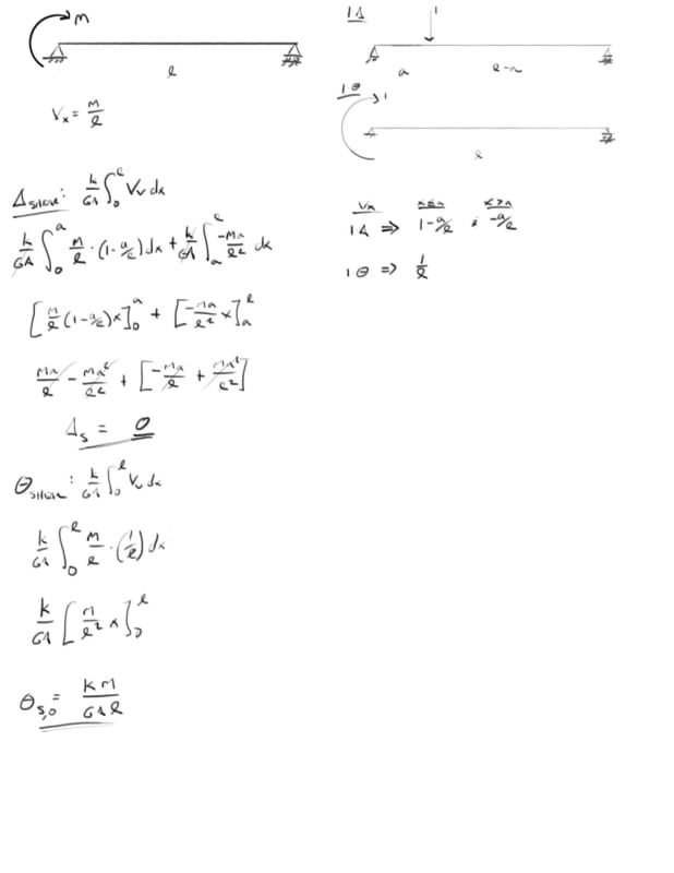
2_e00mlq.jpg


Open Source Structural Applications:
 
Replies continue below

Recommended for you

BA said:
Or are you saying that the bending stresses at the support create a horizontal couple?

Yes, that's exactly how I've been thinking of it.

BA said:
I have to admit that I am having trouble seeing why the slope of the unloaded span (according to theory) has a value other than zero when we know it should be zero...very frustrating.

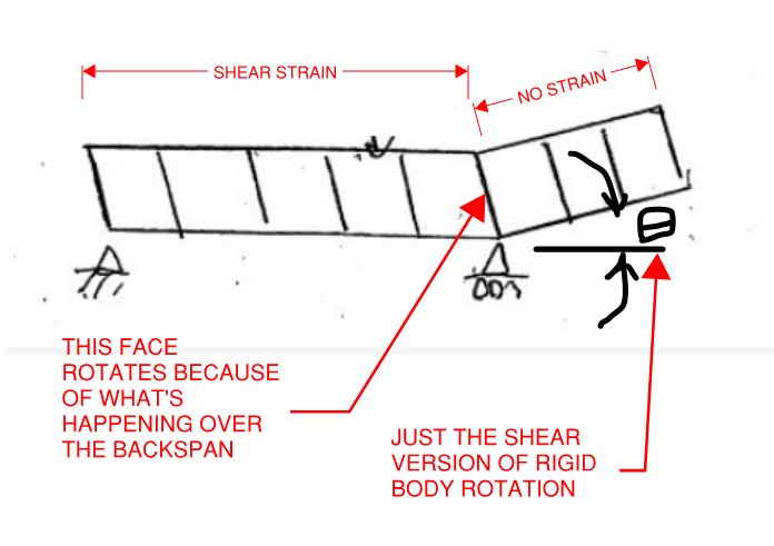
Does this help? I believe that there is in fact slope over the unloaded segment but that that slope is a result of rigid body rotation rather than shear strain which is, as you say, zero there.

c01_nntn9i.jpg
 
KootK said:
1) In general continuity is fundamental to our craft and should be considered.
2) In the context of a thought experiment considering what might happen if continuity were not enforced, it is pointless to enforce continuity.

OK, that's reasonable, let's consider what happens if we allow a discontinuity under the point load at mid-span of a simply supported beam.

I'd say that the segments would rotate about the top point, there would be no shear strain anywhere and no source of any reaction force, so the system would be unstable. I don't see how that tells us much about how the system behaves if continuity is required.

Also if we are using an energy approach we have to consider all sources of strain, don't we? It seems to me that applying energy conservation when you are disregarding the major source of strain energy (flexural strain) might be misleading.

14:51 reply to BA:
I think the bottom sketch is wrong. As the distance between the forces reduces the moment approaches zero, so the deflection will reduce to zero and the vertical planes will remain vertical.

20:19reply to BA:
I agree with that sketch; makes the source of the deflection very clear (to me).

Since it's the weekend, some philosophy:
Why questions in physics when they hit postulates and laws, is like asking why for an axiom in mathematics. Principles are part of the definition of the theory, and physics theories are established when validated continuously by the data.

One cannot explain this principle except by attributing it to observations that forced us to use it axiomatically.

That is true, but it isn't always clear where we hit the postulates and laws. For instance, gravity is often cited as an example of something that is "just the way it is", but there must be some underlying mechanism to how mass interacts with space-time (whatever that is) that results in masses appearing to attract each other. It may be that that mechanism is inaccessible to us, but if we can develop a testable theory about how the mechanism actually works, that would give us a deeper understanding, even if we are still left with the question of why that mechanism is the way it is, and not something else.

As another example, if we define force as mass * acceleration, or if we define mass as force / acceleration, then the other two laws of motion come directly from that, and so does conservation of momentum. And if we are talking about fully elastic systems, and define energy as force * distance, so does conservation of energy. So the fundamental thing here is not the two conservation laws, it is the relationship between mass and force, and between force and energy.

So the message from that is that whilst looking at energy conservation can be useful, considerations of stress, strain and geometry are more fundamental, and come closer to answering the "why" questions.

Doug Jenkins
Interactive Design Services
 
That's interesting BA. I'll suggest a refinement as shown below whereby the point loads are not kept constant but, rather, increased as they come together to keep the applied moment constant. Some features of this arrangement:

OK, I should read properly before replying.

I'd say that when the gap between the two forces reduces to zero then either:
The moment and nett force both reduce to zero, so there is no strain of any sort.
or:
The moment becomes a pure moment and the sections behave as shown, but to do this the applied forces would have to swap from vertical to horizontal, with a separation.

Of course in a real beam the standard "plane sections remain plane" nonsense would stop being even a rough approximation well before the separation distance became zero.

Doug Jenkins
Interactive Design Services
 
IDS said:
So the message from that is that whilst looking at energy conservation can be useful, considerations of stress, strain and geometry are more fundamental, and come closer to answering the "why" questions.

It appears to me that you are still missing something absolutely critical to the arguments that I've been proposing. Let's try it this way:

1) The considerations of stress, strain, and geometry that you mentioned above are all predicated upon the assumption of continuity. I don't think we disagree on that but, by all means, let me know if we do.

2) I contend that continuity itself is predicated upon he assumption of energy conservation. And I feel that I've made a pretty good case for that above. I see energy as the "why" for continuity. If there are other, better why's, I simply don't know of them currently.

3) If one accepts my premise that energy conservation is the "why" that underpins continuity itself, then it becomes evident that energy concerns are, in fact, more fundamental than stress, strain, and geometry. I contend that there is a hierarchy of principles here and that energy is higher up the food chain than continuity and geometry.

In a previous post, I'd laid out my argument as concisely and logically as I know how to do it. I did that primarily for your benefit but it's been a long thread so you may have missed that, I don't know. I'll repeat it here with slight modification and ask that you give it some careful consideration and let me know which parts you disagree with. As you can see, I've presented continuity as a stopover between the core principle of energy conservation and the end result of shear strains manifesting themselves as we've determined they must.

Axioms

1) Nature minimizes energy.

2) Continuity violations cause damage which consumes energy.

Premises

3) 1 + 2 --> Nature will enforce continuity when possible.

4) 3 ---> Loaded materials will organize themselves such energy is minimized.

Conclusion

5) 4 ---> Shearing strains will manifest themselves in a way that minimizes energy.


Now I'll respond to some of the stuff around the margins...

IDS said:
I'd say that the segments would rotate about the top point, there would be no shear strain anywhere and no source of any reaction force, so the system would be unstable. I don't see how that tells us much about how the system behaves if continuity is required.

The particular form that the "damage" would take is immaterial to the argument that I was making. All that matters is that any damage resulting from a continuity violation would consume energy that would not be consumed without the continuity violation. I'm trying to establish that a solution involving a violation of continuity represents a solution in which energy has not been minimized.

This is just one step in the logical argument that I laid out in my previous post. The logical argument, taken as a whole, does tell something about how the system will behave. But this one step, considered in isolation, does not.

-----------------------------

IDS said:
Also if we are using an energy approach we have to consider all sources of strain, don't we? It seems to me that applying energy conservation when you are disregarding the major source of strain energy (flexural strain) might be misleading.

I agree and this was really what I was getting at back on the 7th with the comment below. At the least, I'd think that we could agree that shearing strains must play a role in the energy picture. Whether or not that role can be considered independently of flexure's roll is up for debate I suppose.

KootK said:
Hypothesis: in an extenally loaded thing, each and every strain in every element of that thing must contribute to the external load doing external work.

-----------------------------

IDS said:
That is true, but it isn't always clear where we hit the postulates and laws. For instance, gravity is often cited as an example of something that is "just the way it is", but there must be some underlying mechanism to how mass interacts with space-time (whatever that is) that results in masses appearing to attract each other.

I agree and this is pretty much exactly what I had in mind with the comment below. I feel that continuity is not quite where we hit "postulates and laws".

KootK said:
Part of what I've been trying to get at with the energy/continuity business is that I really just see energy minimization as a further drill down on the continuity concept.


ShearDeformation001_crzn4p.png


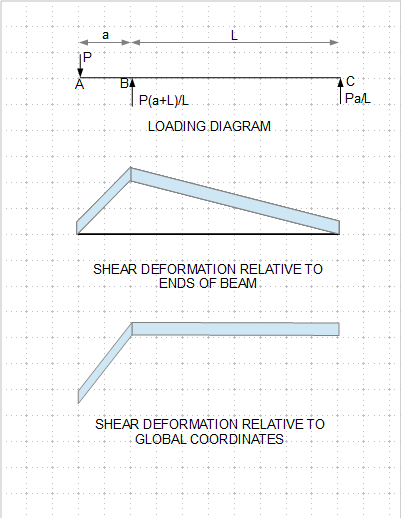
I think I have finally got this issue through my head. For a simple span with cantilever loaded at the end, shear deformation is shown above. A simple span beam with span of L+a, loaded with P(L+a)/L at Point B would have exactly the same deformation (shown in the second diagram). The third diagram is rotated to show deflection relative to a horizontal line (global coordinates).

From the perspective of beam segment B-C, this is tantamount to applying a counter clockwise moment at point B.

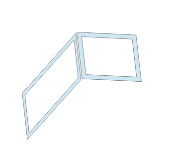
Edit: The end slopes don't show up very well in the above diagram. The following is an enlarged view of the condition at Joint B:

ShearDeformation002_kht257.png
 
BA: I do think there's an important difference. Member AB in your example shows shear, when in the point moment problem the cantilever doesn't have any shear. It just deflects upwards because the slope due to shear deformation is not 0 at the support.

This is similar to a flexural cantilever member with a backspan, where only the backspan is loaded. The cantilever is not loaded but still deflects due to a non 0 rotation at the support. I think we just struggle to make sense of the shear cantilever deflection because it is opposite of the flexure deformation, which our minds have accepted as logical/intuitive.
 
BA said:
From the perspective of beam segment B-C, this is tantamount to applying a counter clockwise moment at point B.

Agree.

BA said:
I think I have finally got this issue through my head.

Yeah, I'd say that you've nailed it. In a way, I think that your non-point-moment example is extra salient precisely because it show that you can get the same phenomenon even without the point moment. Although, as you say, it effective is a point moment on the back span.

 
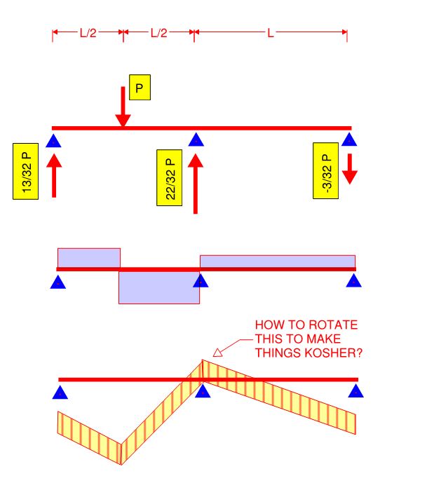
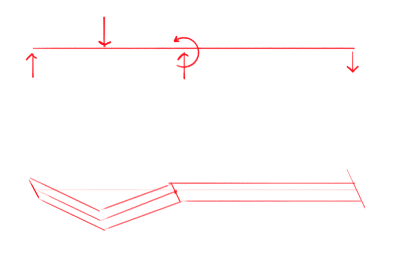
For anyone who may be interested, I present the skill testing question shown below. This had me stumped Saturday morning. Turned a 40 minute gym excursion into a two hour affair as I was scribbling silly diagrams in back issues of Time magazine in between sets. To be clear, I believe that I have the answer already and I'm not stumped any longer. And, if somebody figures it out in thirty seconds, I will feel a little foolish.

c01_o8wsck.jpg
 
I'll play your game. The shear diagram you show is what we would get when considering flexural deformation. However, your deflected diagram shows only shear deformation, so your sketches are not apples to apples.

Are we assuming 0 flexural deformation? If so, the uplift reaction would be 0, and there would be no shear in the right span. The left span deflection would be a 'v'. Did I get it, or am I missing something? (But don't give it away if I am!)


Actually, nevermind. I see my error. That's embarrassing. 1 second...
 
Actually, nevermind my nevermind. I stand by my first post, but to uphold honesty I will leave my second post as evidence that my confidence wavered.
 
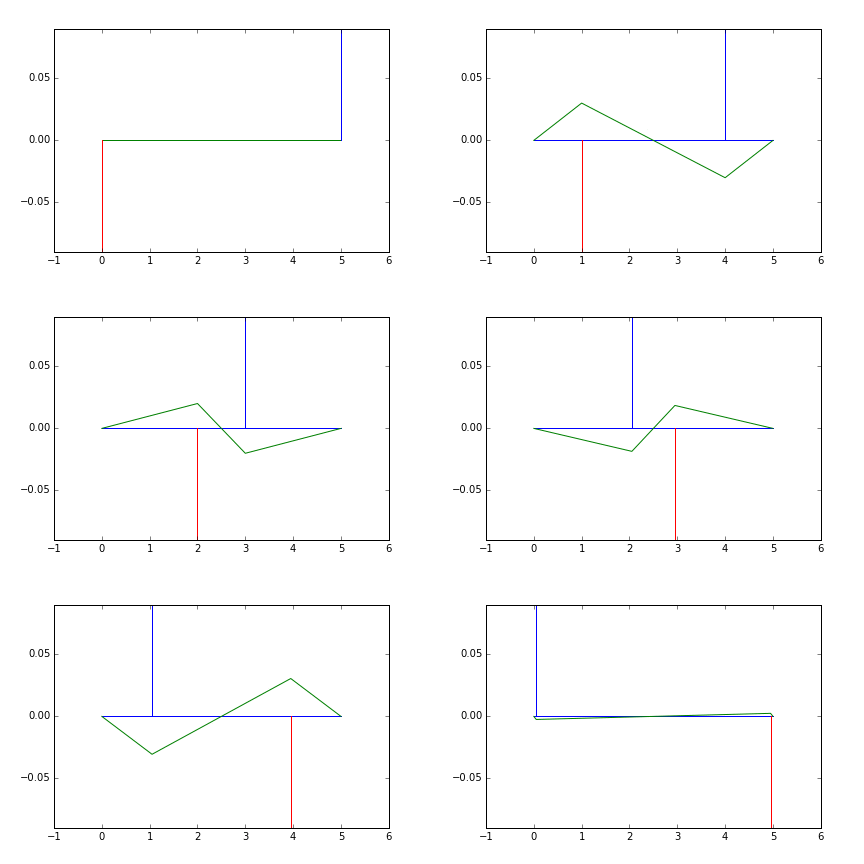
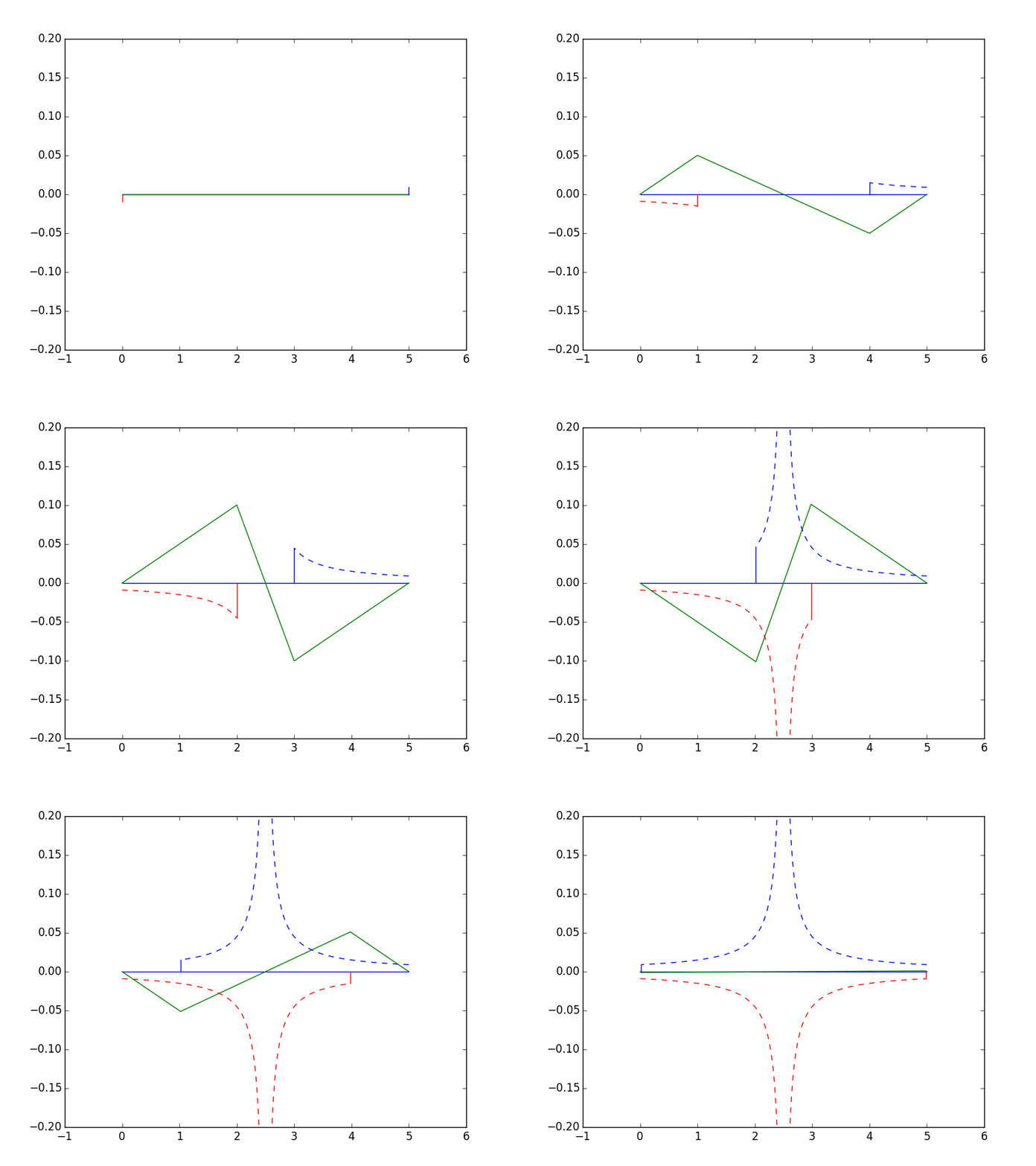
The two points converging and increasing to maintain the coupled moment:

Edit:Link to the code to produce the graphs.

Edit2: To show the loads increasing by L/L', where L' = distance between the loads
eng-tips_point_load_prky8a.gif


when the point loads reach the same location they simply cancel out and there is no impact to slope or deflection, so the section remains unrotated.

Open Source Structural Applications:
 
Celt83 - nice animation, but assuming you are talking about Kootk's post of 11 May 14:51 you haven't increased the force to maintain a constant applied moment, which I also missed in my first response.

Since the force will tend to infinity as the gap approaches zero, plotting the diagram might get a bit difficult.

I will try and respond to other recent posts later today.

Doug Jenkins
Interactive Design Services
 
cal91 said:
The shear diagram you show is what we would get when considering flexural deformation. However, your deflected diagram shows only shear deformation, so your sketches are not apples to apples.

Is this not what we've been doing all along? I certainly have.

cal91 said:
Are we assuming 0 flexural deformation?

Nope. The flexural deformation has to be there or we wouldn't have any flexural shear to deal with as the subject of this super-fun thread. The deformed shape diagrams only consider shear strain however. We could superimpose shear and flexure but then, frankly, I would cease to have the ability to sketch anything meaningful. I don't possess anywhere near that level of skill. And I think that the superposition would obfuscate the salient points of our discussion rather than elucidate them.

 
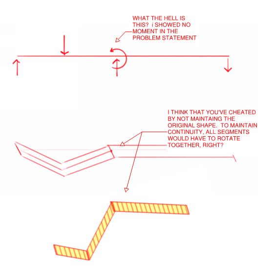
@cal91: in fairness, I think that your close. Just not for quite the right reasons.

 
@celt: Nope. I started at the exact same place though. And, based on prior arguments, was immensely bothered that there would be horizontal strain in a thing with only vertical loads. I came to the conclusion that there could be such a situation that this wasn't it.

c02_etfoye.jpg
 
Status
Not open for further replies.

Part and Inventory Search

Sponsor