Continue to Site

Eng-Tips is the largest engineering community on the Internet

Intelligent Work Forums for Engineering Professionals

  • Congratulations cowski on being selected by the Eng-Tips community for having the most helpful posts in the forums last week. Way to Go!

Shear Deformation - Point Moment 7

Status
Not open for further replies.

Celt83

Structural
Sep 4, 2007
2,083
This is probably something that is very easy and I am way overthinking it.

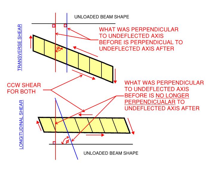
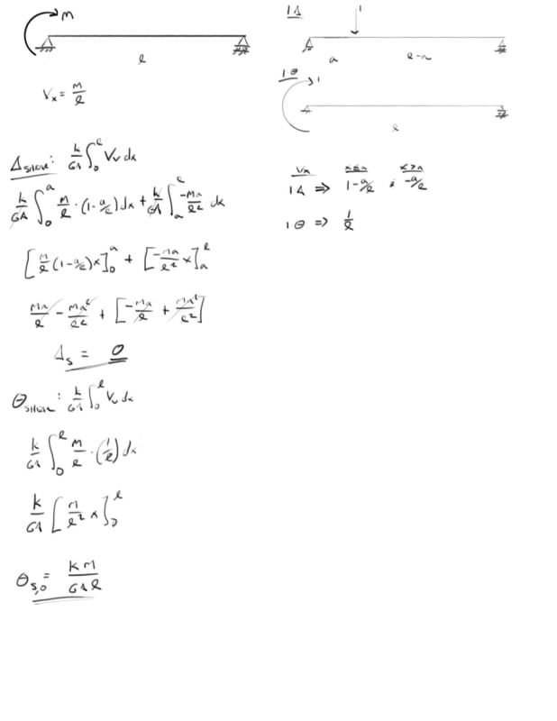
I've done the unit force method which shows that the shear deformation from a point moment is 0 at all locations on a simple span. I've done the same thing to show that the shear component of the slope at any location on the beam is constant = k M / A G L. Here is where I get hung up if the slope is constant and non-zero why is the deflection 0 from a math stand point, the mechanics make sense to me but I'm lost in the math on this one.

I have a great mechanics of materials book by Timoshenko and Young which for me so far has the best break down of shear deformations I've been able to find and in there they present that the slope due to shear is simply dy/dx = tau,max / G = k Vx / A G, which aligns with my unit method solution of k M / A G L.

integrating that once yields: y,shear = k M x / G A L + C1

Initial conditions are x=0, y=0 and x=L, y=0 the first condition yields C1 = 0, however the second condition yields C1 = k M / A G ... so I get that something is missing here which would should result in y,shear = 0 but I am at a loss.

would greatly appreciate any insight on this one.

2_e00mlq.jpg


Open Source Structural Applications:
 
Replies continue below

Recommended for you

The point moment I show was an attempt to simplify the problem down to a single span beam with effects of the internal support as applied loads, which is wrong it's still just a point load, I jumped the gun on that one...whooops.


Open Source Structural Applications:
 
KootK said:
Is this not what we've been doing all along? I certainly have.

Up until your sketch, they have all been determinate systems and thus there hasn't been any reason to say if the load effects are distributed assuming flexural and / or shear distribution. Your sketch, however, is indeterminant.

If we are to look at the shear deformation of a member who's load affects are distributed 100% by flexural deformation, our boundary conditions will be broken.

We have one degree of indeterminancy in your problem. Let's say it is the uplift (right) reaction.

If we were to assume 100% flexural deformation, and we released the right reaction, it would deflect upwards, and bringing it back to 0 deflection would require a reaction force of -3/32 P, and there would be no shear deformation.

If we were to assume 100% shear deformation, and we released the right reaction, it would not deflect at all. Bringing it back to 0 deflection would require a reaction force of 0*P = 0.

If we were to assume 50% shear 50% flexure deformation, and we released the right reaction, the deflection due to shear at the right support would not be 0, and the deflection due to flexure at the right support would not be 0, but added together they would be 0. And thus if we were to look at a diagram of shear deflection ONLY, with internal load affects distributed via flexural deformation ONLY, then the deflection at the right end would not be 0. It would look like this.

Capture_jol0uk.jpg
 
So KootK, going back to horizontal vs vertical shear strains... In the picture I posted above the transverse beam planes that were originally vertical are no longer vertical. The longitudinal plane that was originally horizontal is no longer horizontal. So, is this horizontal shear strain, or vertical shear strain? Or do you accept that it is just shear strain now? :)
 
To provide further light on the sketch I posted above, here's a similar picture. The difference is a rigid body rotation such that boundary conditions are not satisfied, but vertical faces remain vertical.

Capture_k21apr.jpg
 
Even more further light. Or the the most furthest light.

Capture_qac2w5.jpg
 
BAretired said:
A similar problem has been addressed in the following PDF:

Well damn it, I feel like that's cheating. But it is the right answer. Shear flexibility factors into the determination of the shear diagram and reactions so those that I posted initially were incorrect in that way.

 
cal91 said:
Up until your sketch, they have all been determinate systems and thus there hasn't been any reason to say if the load effects are distributed assuming flexural and / or shear distribution.

Yes, and kudos. I lost sight of that once I got deep into the weeds.

I've been rooting around for a practical application for all this and thinking a lot about flexible steel deck diaphragms where we go the other way and assume that the reactions are based 100% on the shear mode
 
cal91 said:
Or do you accept that it is just shear strain now? :)

1) Let me ponder that and;

2) How F%@$&! dare you lay that on me when I took time away from my darling children to prepare the gorgeous sketch below just for you and you didn't even respond.

cal91 said:
KootK when I have time later today I'll respond to you about vertical vs horizontal shear strain

Ohhhh... the unfulfilled commitments.

So yeah, you first cowboy.

c05_ci7fom.jpg
 
Looking at the two span beam as a single span with a point load at the right hand end, and adjusting the load to get zero deflection at the end. With an applied load of -10 kN, and ignoring shear deflections I get:

Sheardef1_d4vrsd.png


Note that the end applied force (or reaction) is exactly as shown in Kootk's original sketch.

Adding in the shear deflections, but leaving the forces unchanged we get:
Sheardef2_plsber.png


Now the right hand end has deflected downwards by the shear deflection, so we need to reduce the force at the right hand end to bring the deflection back to zero:

Sheardef3_f56fwb.png


The magnitude of the adjustment to the end force depends on the ratio of shear deflection to flexural deflection. If the section had infinite flexural stiffness and finite shear stiffness the deflection at the right hand end due to the mid-span load would be zero, so the right hand end load/reaction would also be zero.

I doubt there is a simple formula for the reactions including shear deflection, but it is easy to calculate using standard continuous beam methods, or use the Excel Goal Seek function (which is what I did to generate the graphs).


Doug Jenkins
Interactive Design Services
 
With regard to the Two Point Load Converging Case, Celt 83 had it right the first time but not the second time.

eng-tips_collapsing_point_loads_b7ftfo_mjmjhv.gif


Attempting to keep the moment constant by increasing P could be done but is not necessary because the end reactions are proportionate to P. I was simply trying to show that two loads separated by a short distance tend to result in the beam flattening as they get closer. It could be considered an influence line for two loads positioned each side of an arbitrary point on the beam. When the two point loads converge, as noted by IDS, there is zero load on the beam, hence zero slope.

BA
 
KootK said:
Quote (BAretired)

A similar problem has been addressed in the following PDF:

Well damn it, I feel like that's cheating. But it is the right answer. Shear flexibility factors into the determination of the shear diagram and reactions so those that I posted initially were incorrect in that way.

I don't think it is exactly the right answer. He seems to be using the reactions allowing for flexural deflection only.

Adjusting the reactions doesn't make a huge difference to the left mid-span deflection (at least in the example I looked at), but it does slightly increase.

Doug Jenkins
Interactive Design Services
 
celt said:
if you ended up getting that moment distribution book by Gere there is a good section on considering shear effects.

I did score an ex-library copy and I'll check it out. Thanks for the recommendation.

 
KootK said:
1) Let me ponder that and;

2) How F%@$&! dare you lay that on me when I took time away from my darling children to prepare the gorgeous sketch below just for you and you didn't even respond.

You and I both know you enjoy this problem more than you're darling children!

But yes, you caught me. Please forgive me for my grievous sin. Work got a little busy and I selfishly went home afterwards to play with MY children. To make restitution, I'll put more effort into this post than I would have otherwise.

KootK said:
Ohhhh... the unfulfilled commitments.

Yes, that is my specialty. Ask my wife.

KootK said:
So yeah, you first cowboy.

Ask and ye shall receive.


Let's remember that strain has nothing to do with rigid body rotation. It has nothing to do with global translation. It has everything to do with a member's element's deformation relative to adjacent elements, not relative to some arbitrary outside object (such as a vertical plane, horizontal plane, or your left big toe). Thus we cannot determine anything about a member's strain by it's displacement at all.

How many different types of strains are there, ever?

Two. Normal, and shear.

However, if you want to differentiate strain relative to the orthogonal, geometric axes of a member, than we can, but not in the way you have been proposing.

Let's define P,i as normal strain, parallel to the axis 'i'.
Let's define V,i as shear strain in the plane that is perpendicular to axis 'i'.

Capture_ep36na.jpg


1 - Axial tension/compression (+/- P,x)
2: transverse tension/compression parallel to weak axis (+/- P,y)
3: transverse tension/compression parallel to strong axis (+/- P,z)
4: Positive and negative "beam" shear (+/- V,y)
5: A square cross section becoming a parallelogram (+/- V,x)
6. Weak axis bending beam shear (+/- V,z)


Now, consider a flexural member. On a global level, it's not really shear or axial. For strain, we do not call it "positive bending" strain, or "negative bending" strain, or even "bending strain". If it deflects upwards vs downwards that alone doesn't tell us about the strain. On the elemental level, flexural strain is the same as axial strain. It's either compressive, or tensile. Those are easy to distinguish and define. Compressive strain - elements are closer together / are compressed into smaller shapes. Doesn't matter if it's deflected up or down, left or right. Apply the inverse to tensile strain.

Now let's look at shear.

For argument's sake, lets say this is the usual case where you're right and I'm wrong. If I understand you correctly, you're proposing that there's two different types of beam strain, V,y. There's a horizontal shear strain and a vertical shear strain, both of which are in the plane normal to the axis 'y', but have some distinction from each other at the elemental level. What would "horizontal" strain look like? What would "vertical" strain look like? There must be some difference at the elemental level. We should be able to look at a differential piece and say, yup that's horizontal strain. Or, no that's actually vertical strain. I submit this is what it would look like. (FYI, this is the picture I was thinking of when I said I would respond later to you)

Capture_ncrhg8.jpg


However, this is not how shear strain behaves. The elements don't slide past each other in only either the transverse or longitudinal direction, picking whichever one will satisfy the boundary conditions. On the elemental scale, shear strain is all the same. It is the change in angle between planes that were originally orthogonal.

Celt83 posted this first, from wikipedia.
Capture_mkndtl.jpg


For a beam with horizontal shear deflection, as the point moment example, or a beam with traditional, vertical shear deflection, the strain is the same. It is just a rigid body rotation that is the difference between horizontal and vertical shear deflection. It also just happens that most of our beam examples have exclusively vertical shear deflection. A good amount have horizontal shear deflection, but we don't typically look at the shear deformation of those, and so when we see the horizontal shear deformation in isolation it is unintuitive to us and we think there might be something different going on at the elemental level. But it's not, it's still the same at the elemental level.

So, pardner. Gimme your best shot.

Is this vertical shear strain, or horizontal shear strain, and what the heck is the difference between the two.

Capture_xceswm.jpg
 
cal91 said:
So, pardner. Gimme your best shot.

I shall. But it's bound to be pretty anticlimactic I'm afraid.

Firstly, I agree with all of the technical content of your last post. Force level and rigid body rotation excepted, one shear strained element is the same as the next. And I'd never meant to suggest otherwise.

cal91 said:
Thus we cannot determine anything about a member's strain by it's displacement at all.

I suspect this is the source of our confusion between one another. We're going in different directions. I've no doubt muddled the verbiage in spots but I never wanted to go from a member's displacement to it's state of strain. I wanted to go from it's state of strain to it's displacement and, more precisely for my purposes, that displacement's implications for energy minimization.

cal91 said:
However, if you want to differentiate strain relative to the orthogonal, geometric axes of a member, than we can, but not in the way you have been proposing.

This is the one thing that I disagree with. I can indeed differentiate strain relative to the member axes. And do so in exactly the way that I proposed. Differentiation is just a matter of definition and I did that via a pretty sketch earlier on. So I deny you the right to deny me the right to differentiate things as I see fit. I think that the real question is whether or my differentiation scheme is meanginful. And that's probably the gist of what you were getting at.

So, is it meaningful? Originally, I wanted a classification system by which I could say:

- This kind of strain (transverse) will yield the transverse shear deformations that we're familiar with.

- That kind of strain (longitudinal) will not yield the transverse shear deformations that we're familiar with but, rather, a strange new kind of lateral shimmy that shocks, amazes, and sometimes is not accounted for energetically in our transverse displacement math.

While we were considering simple spans, the classification was meaningful in my opinion. Once we got deeper into the weeds with cantilevers and multiple spans, however, the classification lost it's utility. I think that it still may be valid to say that longitudinal shear within one span will not do work on a transverse load within that span. But that statement involves so many qualifiers that even I don't find it useful any longer.

cal91 said:
Is this vertical shear strain, or horizontal shear strain, and what the heck is the difference between the two.

It's both in superposition as you nicely illustrated previously. And the difference between the two is just as it's been all along: a matter of delineation of the aggregate effect relative to the member axis. It's a difference of little consequence for this example though, I certainly agree.


KootK said:
This is the one thing that I disagree with. I can indeed differentiate strain relative to the member axes. And do so in exactly the way that I proposed. Differentiation is just a matter of definition and I did that via a pretty sketch earlier on. So I deny you the right to deny me the right to differentiate things as I see fit. I think that the real question is whether or my differentiation scheme is meanginful. And that's probably the gist of what you were getting at.

Okay here's my last shot... We can certainly differentiate between the two cases, but there are not different strains going on. They are both shear strains in the XZ plane, V,y. At the elemental level there is no difference, the strains are identical. You cannot differentiate between two things that are identical. I deny you the right :)

What is not identical is their rigid body rotations, and their translations from original undeflected shapes. Like you suggest, it is indeed useful to differentiate between the two. But we cannot call it strain. It is deflection. Horizontal deflection, and vertical deflection. And just shear strain.

 
I don't think that there's any continuing basis for meaningful debate at this point cal91. We agree 100% on the technical points. And the rest just pertains to the semantics of past attempts at classification. Debate is time/energy intensive and I've made it a personal goal to try to extricate myself from things here a little faster than I sometimes do once the technical stuff is in the bag. Must focus on only that which one actually cares about...


cal91 said:
How many different types of strains are there, ever? Two. Normal, and shear.

As an aside, I actually consider shear to be a derivative action, much like bending. When it comes right down to it at an atomic level, I feel that all there is is attraction and repulsion (tension and compression)


Agreed. Not worth the energy hashing it out over minutia/symantics/definitions. Has definitely been enlightening, however.

KootK said:
As an aside, I actually consider shear to be a derivative action, much like bending. When it comes right down to it at an atomic level, I feel that all there is is attraction and repulsion (tension and compression)

This jives well with me. Top left to bottom right corners being in compression, while bottom left to top right corners being in tension results in shear. We'll end in agreement on this note.
 
Status
Not open for further replies.

Part and Inventory Search

Sponsor