BridgeEngineer21
Structural
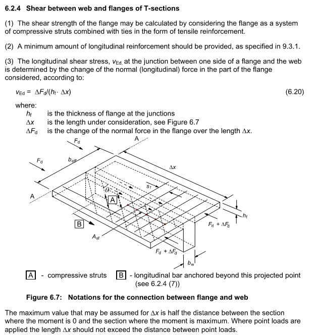
I have a large solid box reinforced concrete beam (h = 5m, b = 4m) with a horizontal construction joint 3.5m from the bottom. I am working with a spreadsheet previously set up by someone else that checked the situation referring to Eurocode 2, 6.2.4:

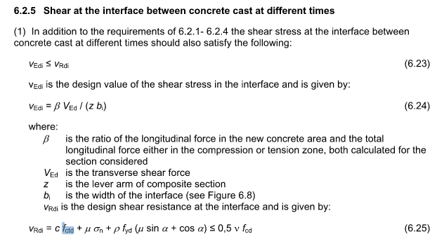
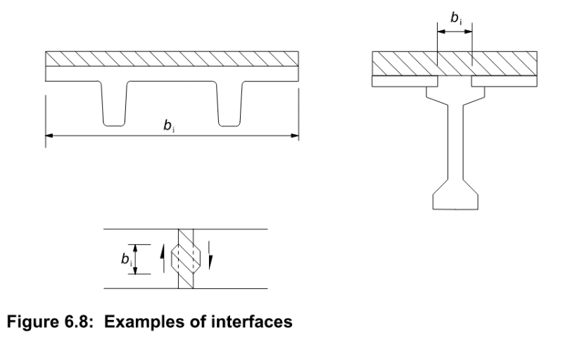
They calculated q = VQ/I, with V = vertical shear, Q = moment of area of the upper 1.5m of the beam, I = Gross moment of inertia of the full depth concrete beam. They then took vED = q/b to get the shear stress across the joint and compared that to the capacity of VRdi, which comes from 6.2.5:

My first issue is it doesn't seem to make sense to refer to 6.2.4 at all, and this whole thing would be most appropriately covered just following 6.2.5. Would be interested to hear any thoughts on that from those familiar with Eurocode.
Secondly, I'm having a doubt about the calculation of q. I know the theoretical principle but have only every applied it in practice to steel beams. Considering that I am checking ultimate loads and the beam will be cracked, using I = Ig doesn't seem appropriate, but I'm not really sure what is best. Since I want to know the actual shear flow in the concrete on both sides of the joint, it seems weird to use the cracked moment of inertia which disregards the concrete below the NA, which will likely end up above the joint. So I am looking for some advice on what I should consider for I here?
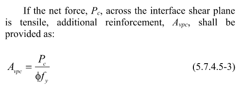
Thirdly, this beam also has a not insignificant and reversible axial force, as well as horizontal transverse shear, which can be applied at any point along the beam's height, which means there can also be torsion. (To be clear, I'm not manually calculating forces in the beam, I already have output from a 3D model with concurrent forces and moments in all three directions at 10th points along the beam). Once I get my shear flow due to vertical transverse shear, do I have to somehow add in axial force, horizontal transverse shear and torsion to get a "total" shear flow across the interface that I would then check against the interface shear capacity? The previous calculation disregarded all of these which seems wrong to me.

They calculated q = VQ/I, with V = vertical shear, Q = moment of area of the upper 1.5m of the beam, I = Gross moment of inertia of the full depth concrete beam. They then took vED = q/b to get the shear stress across the joint and compared that to the capacity of VRdi, which comes from 6.2.5:

My first issue is it doesn't seem to make sense to refer to 6.2.4 at all, and this whole thing would be most appropriately covered just following 6.2.5. Would be interested to hear any thoughts on that from those familiar with Eurocode.
Secondly, I'm having a doubt about the calculation of q. I know the theoretical principle but have only every applied it in practice to steel beams. Considering that I am checking ultimate loads and the beam will be cracked, using I = Ig doesn't seem appropriate, but I'm not really sure what is best. Since I want to know the actual shear flow in the concrete on both sides of the joint, it seems weird to use the cracked moment of inertia which disregards the concrete below the NA, which will likely end up above the joint. So I am looking for some advice on what I should consider for I here?
Thirdly, this beam also has a not insignificant and reversible axial force, as well as horizontal transverse shear, which can be applied at any point along the beam's height, which means there can also be torsion. (To be clear, I'm not manually calculating forces in the beam, I already have output from a 3D model with concurrent forces and moments in all three directions at 10th points along the beam). Once I get my shear flow due to vertical transverse shear, do I have to somehow add in axial force, horizontal transverse shear and torsion to get a "total" shear flow across the interface that I would then check against the interface shear capacity? The previous calculation disregarded all of these which seems wrong to me.

![[tongue] [tongue] [tongue]](/data/assets/smilies/tongue.gif)


