Continue to Site

Eng-Tips is the largest engineering community on the Internet

Intelligent Work Forums for Engineering Professionals

  • Congratulations waross on being selected by the Eng-Tips community for having the most helpful posts in the forums last week. Way to Go!

Shear Friction - Area of Concrete Resisting Shear Transfer

Status
Not open for further replies.

VT17

Structural
Apr 27, 2018
14
Hello All. I've read through several different posts regarding shear friction and I haven't found where this particular topic has been asked regarding shear friction. The closest thread I found was this one: Link.

The question: What is Ac when determining the maximum Vn across the assumed shear plane per Table 22.9.4.4 (ACI 318-19) when a moment acts on a shear plane?

My thoughts: The definition of Ac per chapter 2 is the area of concrete section resisting shear transfer. The name of the above referenced table further makes me think that Ac is the area of the entire shear plane. In other words, if you have a section with a width of "b" and a height of "h", then Ac = b x h. However, if a moment acts on the shear plane where one side of the neutral axis will be in tension, should the depth of the section that contributes to Ac be reduced from "h" to the depth of the compression block "a" so that Ac = b x a? Or perhaps this is being too conservative and "h" should be reduced to "d", the distance from the extreme compression fiber to the the centroid of the longitudinal tension reinforcement?

Thank you in advance for reading.
 
Replies continue below

Recommended for you

VT17, I've battled with this question myself since ACI does not clearly define Ac.

I generally agree with your approach.
There are a few clues that lead me to believe ACI is referring to the entire shear plane and not just the area of the compression block.

1. The title of Table 22.9.4.4 - [Max Vn across assumed shear plane]. - Indicates Ac = area of shear plane
2. R.22.9.4.6 [Where moment acts on a shear plane, the flexural compression and tension forces are in equilibrium and do not change the resultant compression AvfFy acting across the shear plane...] - Indicates the shear plane includes both the tension and compression areas if a moment acts across the joint.

Now the bad news...
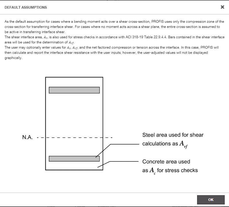
Hilti, which generally offers very sophisticated software, contradicts this argument as shown in the screen shot below.
This picture is from their slab extension software (shear friction) and not their standard dowel/concrete breakout software.
Hilti defines Ac as the compression block area, which in my opinion is not necessary as per ACI.

Screenshot_2024-06-18_134257_gfkt8w.png
 
Interesting question,

I think in most cases the "full" depth (minus cover or minus 3" for unreinforced concrete set against earth, etc.) would apply, the reason is there's generally a reduction in the needed shear reinforcement area when the section is in (full depth) compression. Unless those provisions have changed or been deleted. If you are restricting yourself to just the compression block that's likely quite conservative as the shear is supposed to be sort of a contact through a cracked section kind of thing. Meaning that the (fully developed) rebar holds it together mostly but the aggregate interlock is a factor because the rebar doesn't allow the crack to grow.
 
Thank you CDLD and lexpatrie for your comments.

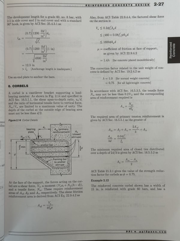
In my attempts to find out examples regarding the use of shear friction, I found the corbel design examples in the PCI Design Handbook and SE Reference Manual. Both of these make the check for the max Vn across the assumed shear plane per Table 22.9.4.4 in ACI. In both cases, based on how the corbel is detailed, they use the distance from the extreme compression fiber to the the centroid of the longitudinal tension reinforcement.

In both examples they use a coefficient of friction that corresponds to monolithically placed concrete. One of the things I personally was worried about was if the calculation for Ac would have to be different if the shear plane occurred at a cold joint subject to a moment. However, these examples leave to believe that the calculation for Ac should be the same regardless of the concrete surface condition (obviously for the calculation of Vn = mu x Avf x fy, the proper mu factor should be used based on the surface condition). And perhaps more importantly, it reinforces my intuition that the depth of the section that resists shear transfer should be reduced to "d". Unless someone else can enlighten me better, I think I will proceed with this method.
 
VT do you mind sharing the example from SE reference manual?

Does it bother you that Hilti doesn't follow this method for Ac calculation?
 
I think that we will not find a definitive answer to that. I never saw an experiment that considers bending with shear, they are always small samples loaded in pure shear.

I guess that this is the best paper on the subject that I managed to find:
Author worked with hilti if I understood correctly.

This is what I got from this paper (please note that I may have misinterpreted it).
The problem here is that there are two possible modes of failure - rigid (mode 1) and non-rigid mode (mode 2).
Rigid mode is not ductile and always happens first. It is basically just cohesion + friction from axial load. No aggregate interlock, dowel action or friction from axial activation of reinforcement can be added.
If this fails, a crack forms. Aggregate interlock and rebars activate at a larger slip (dowel action activates last if I got that right). Once cohesion fails, it can not return. Also, if the crack does not form reinforcement and aggregate interlock can not activate.

Mode 2 occurs after the initial mode 1 failure and it can be avoided only if there is enough reinforcement crossing the joint.

So you can see that one solution for all the situations is not possible. It is also mentioned in that paper that all these mechanisms influence each other.

In my opinion if you have bending you get an initial crack, meaning that only the compression zone contributes to the capacity for mode 1. This is expression for the mode 1 failure:
Capture_scvggg.png

If we look only at the friction part at bending failure - compression stress perpendicular to failure plane is equal to the strength so the right part should usually govern, i.e. 25 % of compressive strength of concrete. This means that the shear force at which mode 1 failure would occur is 0,25*fc*compression area. It seems like a lot to me, but in a way it makes sense, you're stressing the section in a perpendicular direction with a huge force, how is it supposed to slide?

If however it starts sliding, you can not rely on cohesion anymore, but compressed part of the section is still actively resisting the sliding. In addition any reinforcement not stressed to yield will both a) clamp the section and b) reduce the flexural crack so that aggregate interlock increases.
 
How are you trying to use shear-friction where Ac is a concern? The magic of shear-friction is in the steel acting in tension to create a clamping force. The ACI equation for shear-friction is not a function of the concrete area.
 
DTS, table 22.9.4.4 has equations for the upper limit on interface shear strength (which are dependent on Ac).
If Ac is taken as the area of the compression block then you will likely get a reduction in shear strength.

 
CDLD: I'm hoping I attached correctly the picture I took of the example. There are a couple of things about Hilti that bothers me when it comes to how it handles shear calculations. Their shear calcs are a little different compared to what ACI says to do for:
[ol 1]
[li]shear capacity of anchors in a base plate that is bearing on a grout pad[/li][li]concrete breakout strength for shear near an edge when anchors are subject to shear load in both axis simultaneously[/li][li]concrete breakout strength for shear of a group of anchors near an edge when you have one anchor closer to the edge relative to the other one[/li]
[/ol]

At least their calcs are more conservative for the above three scenarios but I'm not surprised that for shear friction they do something different as well. At least for those calcs they are more transparent about it in their software inputs. For the other three I had do go through their calculation report to find the discrepancies.

hardbutmild: I don't have access to the link you provided but I appreciate your response, it's definitely insightful

IMG_6214_yllmmt.jpg
 
I feel like I saw one with shear friction at the base of a shear wall...... that would involve moment/tension on the one end of it, it also involved a particularly large Ac.

Also, that particular Hilti example isn't that for a slab splice?

Not sure I follow that PPI example, they're using shear friction to justify a fully cast-in-place corbel? I guess that explains the 1.4lambda option I've never understood is in the code. Most of the corbels I've dealt with are on precast columns, so they're not exactly my problem (and also, I wasn't the engineer of record, either). I kind of thought there were separate provisions for corbels or strut and tie were more commonly used as the method for them. Shrug.

I can't vouch for this, but the diagrams at least look decent, code language seems to be more or less plausible. Interrupting ads and whatnot, and it's in metric, but it's a slab construction joint for horizontal diaphragm shear if I understand it right.

Shear friction check: A worked example, Thestructuralworld.com website, Jan 28, 2019, accessed 6/21/2024.

As to your 'd' question, I think that would potentially vary, if you held it to the depth of rebar, that's probably conservative in most situations I picture. If you were doing shear friction on to an existing footing, that d is perhaps more literal because that 3" cover to the soil is somewhat expected to be an irregular surface as it's cast against soil, when it came to a wall, I think the depth could potentially be the thickness of the wall, or the 'd' could be considered as the depth to the shear friction reinforcement....

This is a paid seminar but even the synopsis has some value - ICC Seminar, Shear friction dowel design for concrete diaphragms.
 
Seems to me that you'd only want to account for the area of concrete that is actually in compression. If you have a moment on the section, then that is not necessarily the whole area.
 
Status
Not open for further replies.

Part and Inventory Search

Sponsor