Continue to Site

Eng-Tips is the largest engineering community on the Internet

Intelligent Work Forums for Engineering Professionals

  • Congratulations cowski on being selected by the Eng-Tips community for having the most helpful posts in the forums last week. Way to Go!

Shear Lag 1

Mike Mike

Structural
Apr 27, 2019
140
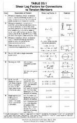
Hi all, what is the minimum weld length for tension members? We are designing a ton of welded knife plate connections for HSS10x10x1/4 tension and compression braces. The LRFD tensile capacity is 371k. The LRFD axial load is +-100k, so we only need (4) 6" long 3/16" fillet welds, and we only need a U factor of around 0.27. But to comply with case 6 in the table below, we have to specify 10" minimum. Why does the table state l >= H? Were shorter welds not tested? Would you be comfortable pushing this recommendation? It seems we have mixed opinions in my office.
1745691078591.png
 
Replies continue below

Recommended for you

The provision that weld lengths should be at least as long as the gap between them (perpendicular to the line of force) has been in the code for a long time.

A commentary from the 9th Edition for its section B3 states:
"...tests (Kulak, Fisher, and Struik, 1987) have shown that flat plates, or bars axially loaded in tension and connected only by longitudinal fillet welds, may fail prematurely by shear lag at their corners if the welds are separated by too great a distance. Therefore, the values of U are specified unless the member is designed on the basis of effective net area as discussed below."
 
Thanks JAE, I spent a half hour unsuccessfully hunting for that reference. I found "Guide to Design Criteria for Bolted and Riveted Joints" Kulak, Fisher, and Struik 2nd edition 1987 and skimmed thru it, but found no reference to our discussion. This appears to be a discussion of research by others rather than original research, but maybe I'm missing something. I understand failures occurring "prematurely by shear lag at their corners" and other complex behavior may be present in greater degree for short welds, but we should provide design guidance in these situations instead of setting minimums. What if the load was only +-10kips? Would you still require four 10" long welds?

What if the code said local buckling or distortional buckling of slender compression elements is too complicated a limit state and just mandated a minimum thickness? Would this be a good way for the code to handle complex behavior?

A few other papers referenced in the 14th edition commentary:
munse and chesson 1963 appears to be behind a paywall
easterling and gonzales 1993 did not test short welds
cheng and kulak 2000 did not test short welds
design guide 21 does not mention short welds
 
Would you be comfortable pushing this recommendation? It seems we have mixed opinions in my office.

YES. That is my short answer though I would can't give a comprehensive argument to support it. I think a plate embedment length equal the largest of the two sizes of a rectangular/square/circular HSS is an excellent rule of thumb to ensure that shear lag is not an issue. I've normally followed this rule myself. Afterall, why mess with what works unless the saving are significant.

However in your case it sounds like the savings are significant and you have done your homework. In which case yes I would be comfortable pushing this recommendation if you have satisfied yourself that shear lag isn't an issue.

If the member is both a compression and tension member then buckling of the member AND/OR the connection will generally be the critical failure point. It's tension capacity will generally be far higher than both these limits as you've likely observed.


In my opinion that member isn't a "tensile member" so TABLE D3.1 doesn't apply. I don't use the same code but that would be my argument. The code I use (AS4100) has certainly design requirements that apply to tensile members that would be absurd if you apply them to members under compression and tension (eg columns)
 
Human, I agree and you are correct. Compressive buckling controls member design, LRFD capacity is only around 140k. We have always just specified the rule of thumb minimum weld length for this scenario but I'm questioning our decision for 2 reasons. One, I want to improve myself, so I'm digging deeper than rules of thumb to understand the limits of what is known and what has been tested. And two, as you mentioned, for mega-projects this means mega-savings. Having the ability to save clients money is an effective business strategy.
 
Human, I agree and you are correct. Compressive buckling controls member design, LRFD capacity is only around 140k. We have always just specified the rule of thumb minimum weld length for this scenario but I'm questioning our decision for 2 reasons. One, I want to improve myself, so I'm digging deeper than rules of thumb to understand the limits of what is known and what has been tested. And two, as you mentioned, for mega-projects this means mega-savings. Having the ability to save clients money is an effective business strategy.
I'm hoping I'm not repeating myself too much here but I agree 100%.

Especially with the digging deeper than rules of thumb. So I would definitely say go for it. It already sounds like you have done suitable research into the issue, you are only hesitant because the guidelines/codes say otherwise.

IMO.

Good engineers can reliably follow the guides/codes. Great engineers know when they can comfortably step outside the guidelines/codes and achieve a better outcome.
 
...
If the member is both a compression and tension member then buckling of the member AND/OR the connection will generally be the critical failure point. It's tension capacity will generally be far higher than both these limits as you've likely observed.


In my opinion that member isn't a "tensile member" so TABLE D3.1 doesn't apply. ...

That's not how this is typically done in AISC. If the connected part has a significant tension, it's checked for tensile rupture. That requires the effective area, Ae, to be determined, which requires the shear lag factor, U, for a case like this.

If the connection had 140k compression and 10 kips tension, then I might omit this check, with an argument similar to yours.
 
Human, I agree and you are correct. Compressive buckling controls member design, LRFD capacity is only around 140k. We have always just specified the rule of thumb minimum weld length for this scenario but I'm questioning our decision for 2 reasons. One, I want to improve myself, so I'm digging deeper than rules of thumb to understand the limits of what is known and what has been tested. And two, as you mentioned, for mega-projects this means mega-savings. Having the ability to save clients money is an effective business strategy.
Assuming Fu = 65 ksi and a 7/16 in. slot width. With 6 in. long welds, I'm getting a tensile rupture design strength of 176 kips. That's a pretty good margin, with Ru/phiRn = 0.568.

I'd still recommend not going with a length < 10 in. due to the problems described below. (If the tensile load was 10 kips, then fine, no argument.)

#1. The provision is in the Specification, which is required by the Building Code. Presumably, you're sealing calcs or drawings, which is a promise that the design is based on the Building Code. In contrast, a guideline in a non-mandatory part of the Manual, like Part 10 for example, could be waived based on engineering judgment. Similarly, analysis details are always a matter of judgment. The question in this thread isn't like that.

#2. You could ask AISC about this, but the Specification Committee would say "no." When I know the authority upstream would say "no," and I don't ask so that I can do it, that's a big red flag.

#3. I've worked on a few forensics projects. If something -- anything -- happens on this project that can possibly be linked to this connection, the other side's forensics engineer will thrash you with questions like:
  • Do you have test results or rigorous analysis for an HSS10x10 with welds shorter than 10 in.? Can you point to some in the literature?
  • These rules have been around for decades, and were recently reaffirmed by being included in the brand new U factors for slotted HSS in Chapter D. The Specification Committee debated this rule and decided to include it. What's your evidence that this group of recognized experts was wrong?
  • Surely, going from 10 in. to 6 in. would cause a reduction in strength, fracture resistance, or some other critical aspect of this connection, right? [Answer = yes, obviously.] Follow-up: Can you say how much?
 
Last edited:
I seem to remember a prof once talking about this and I recall him saying something about unexpected eccentricity of load as a concern with too-short welds. Steel axial members also carry with them initial out-of-plane sweeps or bends and with axial loads applying to these members there could be a moment developed in the weld that wasn't accounted for in design - and welds less than the gap between them would only worsen the stress on the weld.
 
217808,
#1 The specification does not state the length of the weld must be greater than the width of the HSS. In my opinion the l >= H notation notes the limit of applicability of the simple formula.
#2 How do you know AISC would say no? Do you know of anything they've said on this topic?
#3a Yes, an FEA could be performed.
#3b No, there doesn't appear to be any literature on short welds, at least not that I was able to find. Hence the limit of applicability of the simple formula.
#3c Nobody is saying anybody is wrong.
#3d Yes, an FEA could determine how much.
Yes, intermittent welds are a great idea.

Smoulder, only doing 2 welds would certainly increase the shear lag. It's kinda hard to see in the diagram I pasted in my original post, but looking at it on paper it seems to show 4 welds.

JAE, both initial out of straightness and sagging under self-weight. I agree, in real life all connections are subject to incidental loads in all 6 degrees of freedom. But I would not expect these welds to feel anything out of the ordinary. Pretty much just uniformly distributed longitudinal shear. In my opinion the complex stress contours are in the brace, not in the welds.
 

Part and Inventory Search

Sponsor