Continue to Site

Eng-Tips is the largest engineering community on the Internet

Intelligent Work Forums for Engineering Professionals

  • Congratulations KootK on being selected by the Eng-Tips community for having the most helpful posts in the forums last week. Way to Go!

Shear Lug Breakout Failure When Force is Parallel to the Edge 1

Status
Not open for further replies.

MAB70

Structural
Aug 19, 2019
25
Hi all,

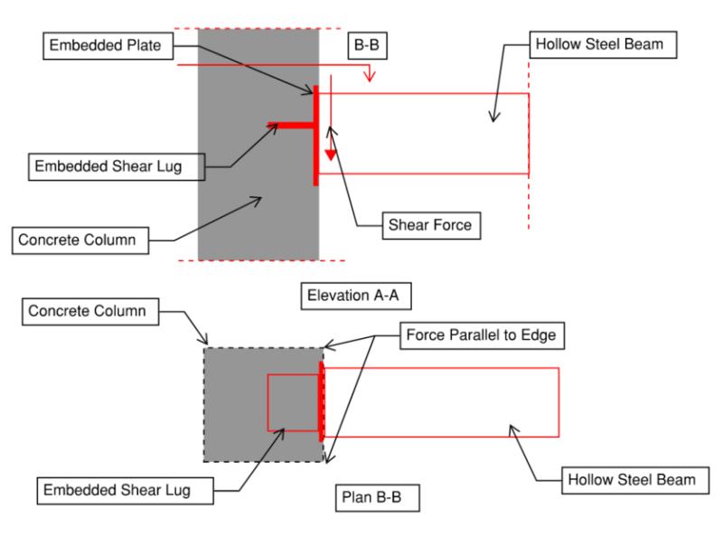
I am connecting a steel beam to a concrete column and having a shear lug to take the huge shear forces from gravity loadings.

I am designing the shear lug as per ACI 349, the code does not discuss the checks of the shear lug incase the force is parallel to the edge (not perpendicular). However, going through ACI 318-11 appendix D, it says for anchor bolts '' The case of shear force parallel to an edge is shown in Fig. RD.6.2.1(c). The maximum shear force that can be applied parallel to the edge, V||, as governed by concrete breakout, is twice the maximum shear force that can be applied perpendicular to the edge, V⊥''.

My question is does this apply also to the shear lug case? Also, can i use the same special reinforcement specified in ACI 318 appendix D to resist the breakout around the lugs? How and what is the breakout perimeter?
Capture_o2r6ru.png


Thanks in Advance
 
Replies continue below

Recommended for you

Is the beam cantilever out from column? For the shear lug, I suggest to use plate with shear studs instead of the tee.
 
Thanks retired13, the beam is simply supported, appologies for the non-clarity on the drawings.

The studs provides a reduced shear strength as per ACI 318 breakout checks, that is why i proposed the shear lug to have greater bearing area.

 
The reasons of my suggestion are:

1) The stem may be in the way of vertical rebars.
2) There is a potential for air voids to form under the stem. The stem and flange forms a dead corner, which is difficult to vibrate.

You may think to turn the tee 90° if it works by strength requirements. But I personally don't trust the shear friction developed in such arrangement.

I don't have code on hand, so my suggestions are purely from practical point of view. If you can provide ACI 318-11 App. D Fig. RD.6.2.1(c), I think more people will join the discussion and offer their opinions.
 
I'm also for studs. Two reasons to add to retired13's list:

1) I think that it's generally safer to stick with what is considered typical practice in a given situation. You know, things that have worked well for others in the past and and for which accepted evaluation procedures exist. For this situation, I feel that is the nelson stud configuration.

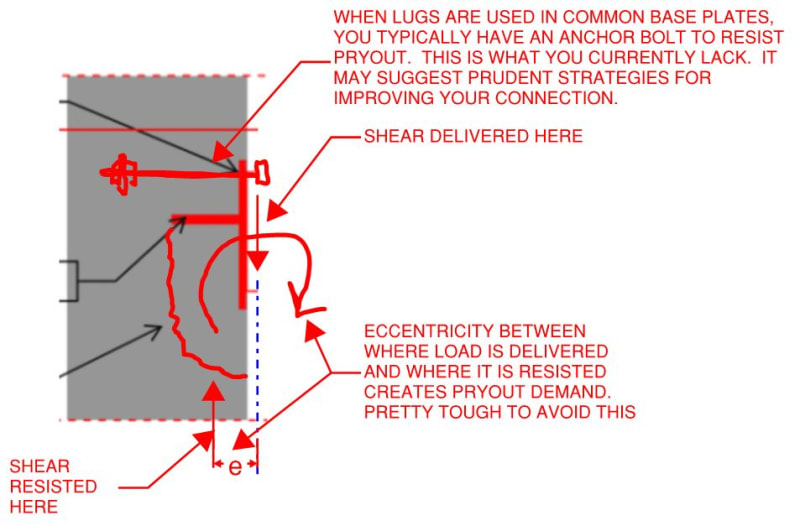
2) In my opinion, your lug situation lacks an important, mechanical component of the connection: you don't have anything to resist the shear pryout mechanism of failure. That would be your anchor bolts in a base plate connection or the studs themselves in a nelson stud application. Not considering this failure mechanism may, in fact, be why the numbers are appearing to work out favorably for you on this. You might be able to get around this if you're willing to consider your HSS to be moment connected to the embed plate. Even that would be a little dubious in my opinion, however, given thermal restraint effects, fitup etc.
 
With really high bearing near an edge like that, does one need to consider some sort of blowout? I understand it wouldn't be blowout from a pure tensile type load on the head of a nut, but there are some really concentrated forces on a shear lug that can produce high pressures where blowout is a concern. Could be a corollary to KootK's shear pryout concern depending on relative lug/plate/beam rigidity.
 
I'll add my advocacy for studs, as well. The shear lug creates a significant discontinuity in both the column concrete and reinforcing. If there's a failure mode for the studs to break out, the same mechanism would apply to the shear lug. The shear lug would likely be worse for breakout, since it isn't locked in to the concrete the way the heads of the studs do and there's nowhere to develop reinforcing between the lug anchorage and the face of the column along the failure plane. If you need more capacity for breakout, add horizontal ties in the column crossing the failure plane to increase the capacity for breakout and/or add more studs.

Rod Smith, P.E., The artist formerly known as HotRod10
 
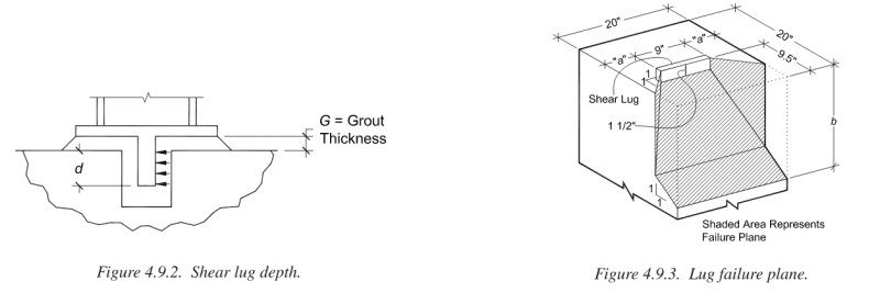
Thanks all for your comments, as i mentioned the studs provides much less shear strength, there is a solved example (4.8) in the AISIC Design Guide 01 - Column Base Plates and Anchor Design_2nd Ed, where shear lugs are used on its own to resist the whole shear force with a defined breakout failure plan which is perpendicular to the nearest edge, the check is based on ACI 349, i thought i can use the same principle to optimize my design, the only difference would be that the force is parallel to the edge not perpendicular.
See below extract from the design guide:
Capture-2_e6cm3q.png


I understand all your concerns and i personally would prefer the studs since the calculation is more defined in the code, however in this case the design is very tight and no matter number of studs we add into, the breakout checks wont work with a limited space.
 
@Kootk, I dont see how pryout failure would form at the shear lug face, the only breakout that would make sense is the shear edge breakout and the concrete capacity for the bearing stress, any thoughts??
 
In the application of shear lug in base plate, the embedment is usually set in the preformed shear pocket, then grouted in place to ensure the positive contact between the tee and the grout. The filling of the grout space is verified through the return of grout from pre-drilled hole(s). Concrete bearing is positive in this case, but not in your application/design, as the potential to have air voids that compromise the quality of concrete bearing. Also, potentially a weak plane is created in the column.

As you go further down the road of engineering, many times you will find construction concerns can be very critical, and influence the way of design. We don't want to see a structure, while satisfies all strength requirements, but failed in service due to lack of consideration on construction practice that may result in increased uncertainty, and lower quality of work. Be mindful in your design.
 
For large load beyond the capacity can provide by the more positive anchorage (studs), I may consider to provide beam seat, if possible, to take away some of the load. It also provides redundancy into the design.
 
Another note besides your design. When shear force is very large with relatively small vertical force, you shall consider embed the base plate level with the ground, as the raised grout tends to be pushed out of position and crumble, resulting in loss of bearing of the column above. Just something to think if you encounter such conditions.
 
Many thanks retired for your valuable comments, i will put that into my considerations.

With regards the beam seat, we will still need to transfer the load of the seat to the concrete so same issue will occur.

I agree with your comments on potential air voids to form in my application, maybe we can introduce a hole in the lug to allow better concrete flow and confinement while pouring and deduct that area from the resisting??

What is really frustrating is the lack of enough research on these tricky connections while they have been extensively used by many contractors and designers by having very different approaches and assumptions. I am just trying to do my best to understand the behavior based on the available research we have.


In my suggestion on beam seat, you will have two connections to share the load. One more thing for you to consider, as you stated before, the beam is simply supported, but if you have large shear force, you might have to put more weldment to the beam connection. For relatively long beam, that weld configuration might produce a moment that is negligibly small, but for shorter span, it could be substantial. The beam seat should help for the latter case.

I agree with you on the lack of guidance and unified approaches for connection design. . But if design work as simple as 1+1=2 we will be all unemployed. The lucky thing is the engineering never been one dimensional, we just have to put our knowledge and training to work on various situations. Good luck.
 
You could pour a corbel to provide the beam seat. This would revert back to standard concrete design that would be more reliable.

The applicability of this depends a lot on the situation, but it is common enough.
 
OP said:
@Kootk, I dont see how pryout failure would form at the shear lug face, the only breakout that would make sense is the shear edge breakout and the concrete capacity for the bearing stress, any thoughts??

1) I stand by my pryout concern per the sketch below.

2) Why is it that you cannot use a long-ish plate with a zillion studs? Whether you use the lug or nelson studs, your ultimate resistance mechanism is the concrete. And, in my experience, it doesn't take all that many studs before you've fully mobilized the concrete with that solution to just as great an extent as you would with the lug.

3) What are the loads that you are delivering to this connection?

c01_lhinfs.jpg
 
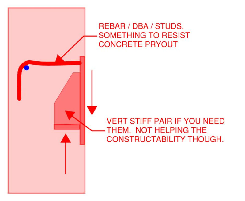
I still do not favor this connection typology over studs but, if I were forced to do something like this, here's how I'd adjust it up to address the pryout issues.

Note that this is to effectively construct jayrod's corbel but to put it inside the formwork. While I very much like the concept of using a true, external corbel, if you're already enthralled to your contractor, I'm sure that they'll veto such a thing because of the formwork costs.

c01_cai4ov.jpg
 
KootK's sketch bring out another monster - shear friction.

The reaction developed under the stem tends to chip the concrete away in a manner similar to beam seat with concentrate load on notched concrete wall. Shear friction capacity of the concrete is to be evaluated, and more often than not, special reinforcement is required to resist the force that causing shear, and to prevent the failure of concrete in un-predicable and brittle manners. Note that the critical shear plane is usually steeper than 45°, measured from column face.
 
[blue](OP)[/blue]

My question is does this apply also to the shear lug case? Also, can i use the same special reinforcement specified in ACI 318 appendix D to resist the breakout around the lugs? How and what is the breakout perimeter?

You are comparing apples and oranges. Appendix D is not applicable here. And really neither is the AISC Design Guide #1. DG #1 has been found (in testing) to overestimate capacity in certain circumstances. The reference to use is this:


And it takes into account edges (as far as the failure planes go).

As far as reinforcing the connection goes (where capacity cannot be met).....not sure I'd try that. I'd just make the lug bigger.

I vote for the studs too (if possible).
 
Status
Not open for further replies.

Part and Inventory Search

Sponsor