Continue to Site

Eng-Tips is the largest engineering community on the Internet

Intelligent Work Forums for Engineering Professionals

  • Congratulations KootK on being selected by the Eng-Tips community for having the most helpful posts in the forums last week. Way to Go!

Shear Pins - Ratio of pin OD to Shear dia, good practice 7

Status
Not open for further replies.

EmWaa

Mechanical
Aug 17, 2023
2
Hi all,

I have been searching, fruitlessly, for good practice guidelines when it comes to shear pin design and the ratios to set the pin OD and shear dia to. We deal a lot with retrofitting solutions, so unless I can persuade the client to bush this particular lug the OD of the pin is set. They want to change the material to 4140 from bronze, which would be a good choice but the increased strength means the OD to shear dia is a big step change: 35mm down to 14.5mm. Eyeballing this it looks too pinched for my liking, but I can't find anything that gives guidance of maximum ratios for setting pin dia to shear dia.

Are there guidelines that people stick to? Or could you have a 75mm dia pin and a 15mm shear dia and there are no adverse effects?

TIA.
 
Replies continue below

Recommended for you

The important part is the shear diameter determined by the desired failure shear. I would think the pin diameter has no or little influence.

Ted
 
Ditto on hydtools's guidance: you should size the pin based on the required shear load plus a design margin (safety factor). The design margin may be dictated by standards/requirements of the industry or application, i.e. human vertical lift/life critical. Choose your material to match the shear strength requirement and environmental conditions.
 
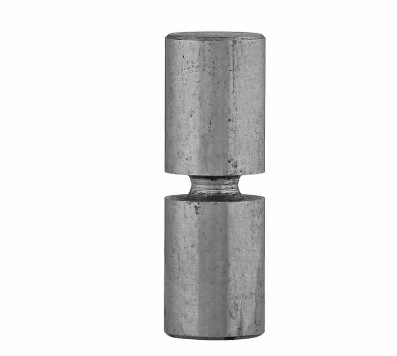
Is that groove in the middle of the pin to 'force' a particular failure to cause failure load to be a more defined value?

-----*****-----
So strange to see the singularity approaching while the entire planet is rapidly turning into a hellscape. -John Coates

-Dik
 
The shear diameters will vary inversely as the square root of the material shear strengths for the same shear failure load.

Ted
 
Size the pin to accommodate the range of shear values that the hub is designed for. If this pin is being inserted into a coupling/flange/sprocket/etc. then bore the same pin hole diameter and turn down the shear diameter. This way you only need to stock one shear pin rough stock, instead of several. Of course, if you are providing shear pins for a wide range of couplings, it would be wise to choose a couple of pin diameters.
 
Thanks... I didn't know that shear pins have a 'notch' all around like

Clipboard01_thbwbr.png


Is the shear diameter the diameter of the 'notch'? and is it's purpose to force a 'brittle' failure that is more easily calculated?

-----*****-----
So strange to see the singularity approaching while the entire planet is rapidly turning into a hellscape. -John Coates

-Dik
 
Is the pin intended to be a "fuse" to fail at a defined load level (within a range, not higher or lower)? Like a fuse pin on an aircraft engine mount?

To me the only purpose of the reduced diameter area is to provide a fuse function; otherwise just make it a straight pin.
 
Mint's advice is good, but the op should also locate the Browning catalog to get an idea of how to translate "torque ratings" to the shear pin area. L/D of the pin vs. load is another thing to copy from the Browning shear pins - you want the pin big enough that the ends stay stable and the bearing area doesn't yield, and the pin failure happens primarily in shear, not bending, thus not destroying the hub.

see
they have links to the catalog pages that may prove helpful.
 

I'm not certain, I don't design shear pins, and use dowels to resist a load. I've always considered both to be shear pins (maybe my recent understanding is incorrect). I suspect true shear pins are like a 'fuse', and that is their purpose.

-----*****-----
So strange to see the singularity approaching while the entire planet is rapidly turning into a hellscape. -John Coates

-Dik
 
Thank you to everyone for your input - appreciated :)

@SWComposites @Hydtools, yes this is a fuse pin to prevent overload being transmitted into an expensive, safety critical, section of the machine. The shear dia will indeed be set based on the critical force at which the pin needs to undergo brittle failure to save damage further down the load path, in the same manner as an aircraft fuse pin in the undercarriage/ engine mount arrangement etc. What I am hoping to find out is if the ratio of shear dia to overall pin dia has a tipping point, or is any ratio acceptable with no adverse effects. Could you theoretically have a 200mm dia pin with a 20mm shear dia, for example and nothing unexpected occur in-service, or is there a general rule of thumb that says you should aim to have this ratio as 0.3 < ratio < 0.5, or something of the like? Or thinking about it is it simply what is practical in terms of machining and getting an suitable finish in the neck radius to maintain the shear force it will break at that limits the step change?
 
It would seem that pin diameter to shear diameter would determine a practical groove width to machine so that the length of the reduced diameter does not create a length getting the failure feature into a length that creates a failure in bending mode rather than pure shear.
An observation: a 4140 shear pin may cause more surface damage in failure than the bronze material. Just a thought.

Ted
 
We used pins in double shear and made out own (Ni alloy).
We selected a smooth OD to be about 33% over strength and then used the groove depth to tune each lot depending on the actual mechanical properties.
We liked the grooves to be ~10-15% of the OD deep and the width was about 2/3 of the depth.
We found these grooves to be very reliable.

= = = = = = = = = = = = = = = = = = = =
P.E. Metallurgy, consulting work welcomed
 
Ed... what is the profile of the groove? Does it have a rounded bottom, or is it a V-notch. I can see the rounded bottom having better fatigue resistance (if needed) and the V-notch having a better controlled load capacity. I don't design them, I'm just curious.

-----*****-----
So strange to see the singularity approaching while the entire planet is rapidly turning into a hellscape. -John Coates

-Dik
 
Cautionary note - be careful with sharp notches as these pins can be subjected to stress reversals and fatigue crack growth, also use a relatively good finish to avoid crack initiation points. Further point, a larger shear diameter to pin diameter allows for a bigger/better radius to avoid stress concentration near the shear diameter.
 
Thanks... maybe sharp is not a good idea.

-----*****-----
So strange to see the singularity approaching while the entire planet is rapidly turning into a hellscape. -John Coates

-Dik
 
They were full radius, anything sharper was unpredictable.

= = = = = = = = = = = = = = = = = = = =
P.E. Metallurgy, consulting work welcomed
 
Thanks, Ed... gathered that from dvd's comment... narrow rounded bottom is likely the best.

-----*****-----
So strange to see the singularity approaching while the entire planet is rapidly turning into a hellscape. -John Coates

-Dik
 
Status
Not open for further replies.

Part and Inventory Search

Sponsor