Eng-Tips is the largest engineering community on the Internet

Intelligent Work Forums for Engineering Professionals

Shear reinforcement in two way slab 8

Status
Not open for further replies.

mrzift

Structural
Jun 20, 2020
17
0
0
AU
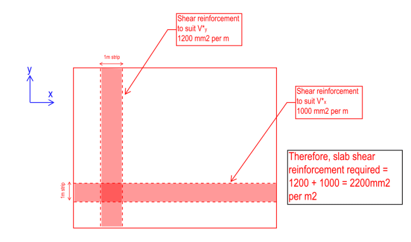
In a two slab (supported on walls), if designing manually using strip methods, should the shear reinforcement required for x direction (Asx) be summed with the shear reinforcement required for the y direction (Asy). The total area (As) be applied to the critical regions?

Otherwise, is it safe to simply design a strip for the maximum shear force (whether its in the x or y direction) without summing up the As.shear required for both directions?

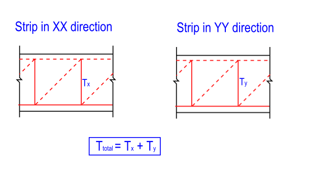
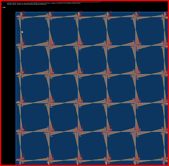
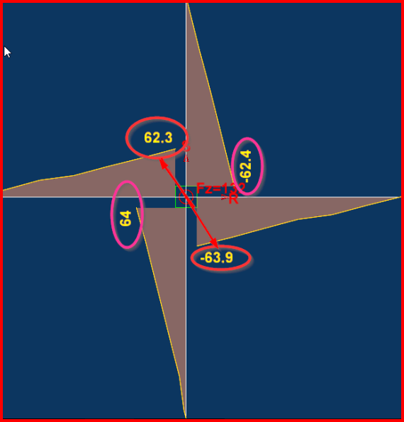
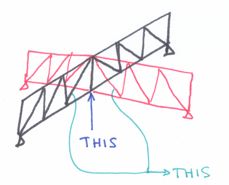
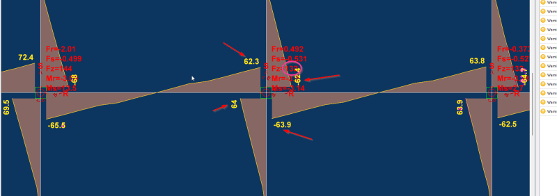
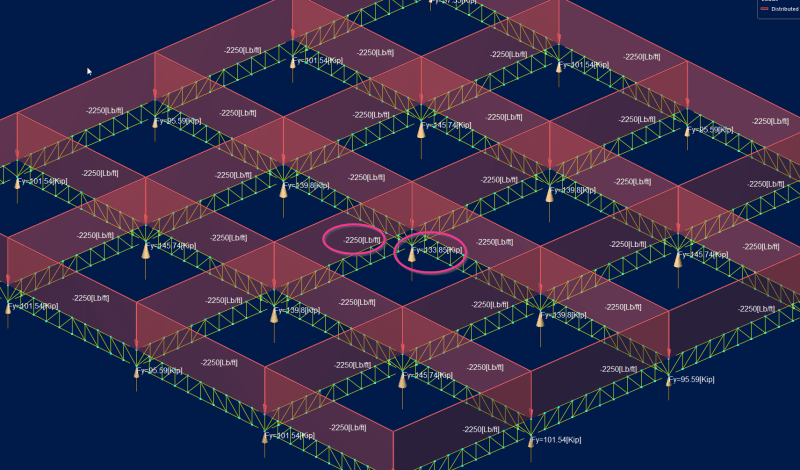
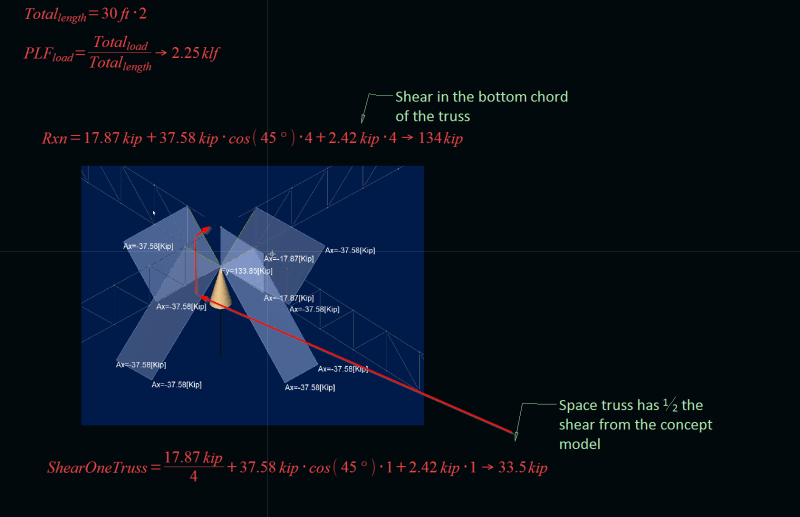
This is an issue that has caused a lot of confusion in my office with many clashing opinions. In a strut and tie model, each direction has a vertical tension force that needs to be resisted, so it does make sense to me to design the slab for a sum of the shear. See diagrams.
Slab_shear_bgq0i4.png


Slab_shear2_hrt7jx.png
 
Replies continue below

Recommended for you

I would say that you need to add the reinforcement to get the total amount in the area where both those are needed, i.e. in the part where strips are intersecting - I really doubt the amount of reinforcement is large along the whole slab. It's unusual to see such a large shear reinforcement in a slab, I'd preffer a thicker slab in this case.
 
What sort of situation is this, where you are designing two way slab by hand, with shear reinforcement in both directions?

I have occasionally added shear reinforcing at the edge of two way slabs, but I’ve never needed shear reinforcement in both directions. Typically adjacent to supports you have little shear flow in the o perpendicular direction.
 
The analysis is done using FEA plate modelling.
Whats done manually is the reinforcement calculation for a 1m strip.
 
Are the walls occurring in both directions? (seems odd). If the walls are only in one direction, wouldn't the slab behave more like a 1 way slab. Can you provide sketch showing the walls? In general I have never added the shears as you are describing.
 
Sometimes they do. Eg punching shear reinforcement.

But a whole slab supported on walls needing shear reinforcing in both directions? What is the structure? Maybe it’s something the rest of us just aren’t familiar with?
 
I appreciate shear reinforcement in slabs is not cost effective though for this slab there is a limit on how much I can increase the depth.
The walls are in both direction. The structure is an underground vault with large axial forces going through the slab.

Ignoring shear reinforcement for a moment, let's say the slab was thick enough, you would have the concrete capacity on its own to resist shear force.
In the case mentioned in the sketch above where you have two intersecting strips, should the concrete capacity be checked individually in each strip and no further checks? i.e Vuc.x > V*x and Vuc.y > V*y

 
Yes, perpendicular shearing forces are additive. If a strip is already at the point of shearing failure in one direction, adding shear force in the perpendicular direction will make the situation worse. The way shear forces combine is nonlinear, so using a linear addition of reinforcement should be a conservative approach.

However, shearing forces are usually concentrated at supports, away from intersection walls. Are you experiencing larger combined Asx + Asy shear forces in some areas compared to the worst-case Asx and Asy forces alone in the critical locations, especially in the central zone of support walls?
 
@Tomfh, sweet, thanks for clarifying that. The issue is I couldn't really see this issue covered in the literature to justify my position on it.

In some critical areas, yes I have larger combined Asx + Asy than the forces acting alone. The loading arrangement and layout of the slab is more complex than the original sketch.
 
I just ran into this recently as well mrzift, curious if the shear reinforcing was in (2) strips was additive or not. Great question, thanks for spawning the thread.

With the recent changes to ACI 318-19, I think shear reinforcing in heavily loaded (2) ways slabs and mat foundations is going to become more and more inevitable. Going from 2 root f`c to less than 1 root f`c really hurts and makes slabs SUPER thick to omit shear reinforcing.

Anyways, I will put myself in camp shear reinforcing is not additive at intersecting strips, but no hard evidence to back up my inclinations.

Reasons for not additive:

[ul]
[li]Consider a design strip without shear reinforcing, there is no consideration given to concrete being shear at the intersection of design strips (similar to what you alluded to earlier in the post)[/li]
[/ul]

[ul]
[li]Design strip shear forces account for 100% of the force in each direction as I understand[/li]
[/ul]

If you were to sum up for each direction, the X direction would have 100% of the total shear in a strip and the Y direction would have 100% of the total shear in each direction for an evenly loaded square 2 way flat plate.

strips_yvs2sq.png

strip_shear_tsvfm4.png

strip_shear_close_miy3jh.png


In the images above, you can see each principle strip direction has ~100% of the total shear force calc'd by hand.
The strut and tie method would therefore be designing for 2x the load if you did a strut and tie model for each direction and then added the results together.

I had reached out to Bentley RAM concept on this about a month ago, no response. I will follow up with them tomorrow if I have time. Concept seems to show shear reinforcing being additive at overlapping strips. Not sure if this was intended or not.

S&T
 
@sticks I do not agree. Imagine a figure below.
001_g47ozg.png

If you have this type of structure, what do you design the vertical element at the connection for? The one where i placed a blue pointer. When looking at concrete, it has two different struts (green arrows on my figure), but reinforcement needs to be able to take ALL the vertical load.
It's different when you look at an element without vertical reinforcement because failure opens two different planes of failure so it's more complex I think. If vertical reinforcement is needed there is no doubt - vertical reinforcement needs to take the whole force.
What you show on your figure looks like a punching problem to me.
 
Hardbutmild,

I completely agree, if you were to do this through a space truss type analysis, you absolutely must design the vertical element for what ever forces appear through analysis.
What I was trying to get at, when we design for one way shear with our typical design strips in concrete, you consider 100% of the force in each direction. You would not do this in a space truss type strut and tie analogy.

In the example I posted before, I have only applied 150psf (12inch concrete slab self weight) on 30'x30' typical bay. Total load in an individual bay is 150psf*30ft*30ft = 135kip.

When you analyze with concrete design strips in one direction, you get one way shears of 64kip + 62.4kip = 126.4kip (close to the 135kip, just off of design strips in concept) which is 100% of the total load in one direction.
Same thing for the other direction, 100% of the load.

2024-05-29_07_53_13-concrete.cpt_-_RAM_Concept_2023_o7uye1.png


With the space truss, strut and tie analogy, you would not be doing this, you would be designing for the total load applied over the area. Below I applied 2.25kip/ft of dead load over a 30ft x 30ft typical bay (yielding similar results to the RAM concept strip example.

2024-05-29_07_56_30-RAM_Elements_iuhtui.png


In this case, shear on one end of the space truss is 1/2 that from the design strip methodology the concrete utilizes.

2024-05-29_08_13_21-Sketchulation_v2024.01.24.00_wic8id.png


Hopefully I've made my point clear, trying to prove this to myself too [bigsmile]

To address your comment "What you show on your figure looks like a punching problem to me." The results shown are purely one way shear in the design strip. Of course punching is also a concern, but let's focus the discussion on one way shear for now.


S&T
 
I completely understand the need for shear reinforcing in flat plates near columns, however requiring shear reinforcing away from the columns is virtually unheard of (exception: shear reinforcing may be required when there is tension in a slab due to walking column tension strut forces, etc.) When we need to use shear reinforcing in slabs we always use “studrail” reinforcing. Using conventional reinforcing steel stirrups will be far too labor intensive and costly.
 
@sticks:

Your latitude and longitude design strips are aggregating stresses over the same area so the total shear in either direction will be equal.

My understanding is the strips are each designed independently so the designed reinforcement in any strip is for that strip/direction. Technically while you may be able to double dip on vertical stirrup legs contained within both strips I do not believe the current code intent allows for that.

"Design strip shear forces account for 100% of the force in each direction as I understand"
I disagree with this statement in a traditional equivalent frame calculation that may be the case but in the 3D FEM model the strip is integrating the element stresses contained within it's bounds and normal to the plane of the panel cuts. You have overlap for full width strip conditions but the stress fields being integrated are different.
 
sticksandtriangles said:
but let's focus the discussion on one way shear for now.
Why look at the problem that is quite clearly a punching problem then? Maybe I understood the problem wrong, but I thought we're talking about problems that are not D regions. What you're talking about is quite clearly a loaclized problem... you do not need to check standard shear here, you need to check punching.
 
Cliff said:
however requiring shear reinforcing away from the columns is virtually unheard of

Have you checked out 318-19? Where I work, it has been adopted and it’s a bit ugly. Not all slabs need one-way shear reinforcing, but many heavily loaded ones do.

Celt83 said:
"Design strip shear forces account for 100% of the force in each direction as I understand"
I disagree with this statement in a traditional equivalent frame calculation that may be the case but in the 3D FEM model the strip is integrating the element stresses contained within it's bounds and normal to the plane of the panel cuts. You have overlap for full width strip conditions but the stress fields being integrated are different.

I agree that a 3D FEM model integrates the strip stress to yield a strip design force. As I see it, though, the strip is a construct to allow us to easily design two-way slabs without having to review stress plots. With strips in two directions, we are essentially doing a design in each direction, similar to this thread where RAPT mentions this.


2024-05-29_12_04_56-two_way_slab_design_-_Structural_engineering_general_discussion_-_Eng-Tips_kjf3vr.png


hardbutmild said:
Why look at the problem that is quite clearly a punching problem then?

Discussion for discussion's sake, hardbutmild. Join me in being a philosopher; let’s get to the bottom of this maybe somewhat silly idea.

Please poke some holes in the posts/images I put above, I still haven't seen anyone address the following and would be happy to change my mind if there is some solid evidence to the additive idea camp:

- Consider a design strip without shear reinforcing, there is no consideration given to concrete being shear at the intersection of design strips (similar to what you alluded to earlier in the post)
- What am I missing in the space truss analogy that I posted. To me, there is 1/2 the shear demand as predicted by the strip design methodology.


S&T
 
okay, I’ll discuss philosophically.
The example that you posted is not solved by either one or two strips - this type of shear is deisgned for reaction along 4 faces, so even the 1 strip idea that you posted will give you the wrong force for design. considering shear as in not punching (if crack can be inclined in a diagonal direction) must be designed for a resultant - what you showed can not crack at the intersection of the two strips in both directions, it’s going to fail by the formation of a circular crack and what a surprise, the whole shear stress along that control perimeter must be acounted for. try making your mesh 10 times smaller in your example, do you get the same result?

EDIT: I found a paper that discusses this: It's about biaxial shear in columns, but there is no significant difference I believe.
The main point is that a check should be made similar to biaxial bending moment check, i.e.
(Vx / Vx,capacity)^2+(Vy / Vy,capacity)^2 < 1
This would suggest that there is some sort of shear interaction, it is not an independent problem.
 
Status
Not open for further replies.
Back
Top