Continue to Site

Eng-Tips is the largest engineering community on the Internet

Intelligent Work Forums for Engineering Professionals

  • Congratulations IDS on being selected by the Eng-Tips community for having the most helpful posts in the forums last week. Way to Go!

Shear reinforcement in two way slab 8

Status
Not open for further replies.

mrzift

Structural
Jun 20, 2020
17
In a two slab (supported on walls), if designing manually using strip methods, should the shear reinforcement required for x direction (Asx) be summed with the shear reinforcement required for the y direction (Asy). The total area (As) be applied to the critical regions?

Otherwise, is it safe to simply design a strip for the maximum shear force (whether its in the x or y direction) without summing up the As.shear required for both directions?

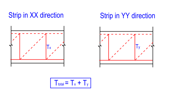
This is an issue that has caused a lot of confusion in my office with many clashing opinions. In a strut and tie model, each direction has a vertical tension force that needs to be resisted, so it does make sense to me to design the slab for a sum of the shear. See diagrams.
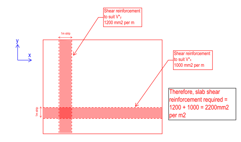
Slab_shear_bgq0i4.png


Slab_shear2_hrt7jx.png
 
Replies continue below

Recommended for you

Yes, I would expect something like the root sum of squares, as it accounts for the longer diagonal length in the combined direction, rather than a straightforward linear addition.

Alternatively, you could directly check the critical shear plane, such as a diagonal across the square that produces the highest perpendicular shear stresses, and evaluate that plane for one-way shear stresses. You will have a certain concrete area and tie area perpendicular to that plane, which can then be assessed.

Regarding the punching shear case, I agree it appears to be a more standard case of two-way shear around a column, which is slightly different from the interaction of perpendicular shear in two overlapping strips.
 
hardbutmild said:
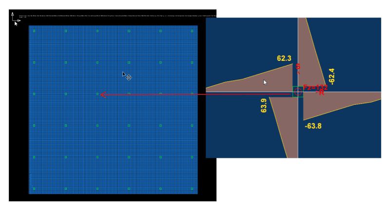
try making your mesh 10 times smaller in your example, do you get the same result?

Yes, pretty much the same exact results. 2ft max meshing yields this:
2024-05-29_22_14_57-Document1__-_Bluebeam_Revu_x64_z6xddr.png


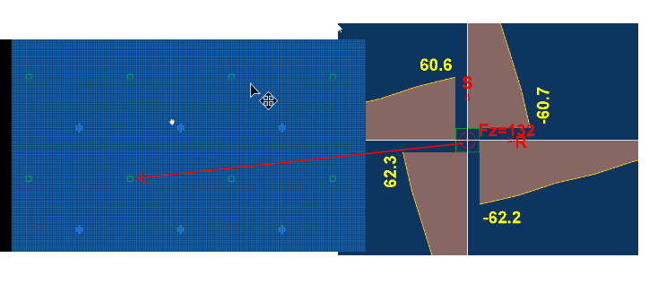
A finer mesh 1ft max meshing yields this:

2024-05-29_22_24_16-Document1__-_Bluebeam_Revu_x64_zoij8p.png


The biaxial (why didn't they call this bi-directional) shear in columns paper you linked, I guess I could see a parallel to it with slab strip shears, but again, the shears in the columns are the shears in the column. There is no 100% of the shear in both directions type element going on here like in the slab strip design methodology. Also, ACI 318-19 does not appear to address this for slabs.

(It is an interesting article though, I did not know that ACI 318-19 now has some checks for biaxial shear. )

mildbuthard said:
this type of shear is designed for reaction along 4 faces, so even the 1 strip idea that you posted will give you the wrong force for design.... it’s going to fail by the formation of a circular crack and what a surprise,

This feels like you are going back to the punching shear item, lets ignore that for now. Assume that shear reinforcing for one way slab shear checks was required right the middle of the slab, no punching shear problems in sight.

tomfh said:
Alternatively, you could directly check the critical shear plane, such as a diagonal across the square that produces the highest perpendicular shear stresses, and evaluate that plane for one-way shear stresses. You will have a certain concrete area and tie area perpendicular to that plane, which can then be assessed.

I agree, but you could similarly draw a strip diagonally the other perpendicular direction and get the same overlapping strip item that we have been discussing. If one strip needs x amount of shear reinforcing and the other direction needs y amount of shear reinforcing at an intersection, do you need to add these together?


S&T
 
I am being taken a little out of context here with the quote from my previous post.

Yes, the total effect in a panel in each direction will be 100% and be basically the same for Equivalent Frame in the 2 directions versus FEM.

But FEM will show the distribution of the effects over the width of the panel in both directions which Equivalent Frame cannot. In RAPT we at least break that down to column and middle strips to try to mimic the FEM distribution, but still with very wide strips (half panel width for each for a square panel).

As long as the designer breaks the FEM result down to sensible width strips (maybe 10% of panel), they will get the logical shears in each area in each direction. This will not be 100% in each direction. In fact in a uniformly loaded slab, in the middle area (what would normally be middle strip + moment area), it will be about 50% in each direction.

if however they do what many designers do and just consider a single full panel width strip as the PTI suggests for PT slabs (i will not rant on further on that logic here) then they are basically getting an averaged Equivalent Frame result which gives no idea of the actual shear requirements in each area of the slab in the 2 directions.

 
Thanks all for your input, it's been a very interesting discussion.
I did ask the technical team behind the software im using for FEA (SpaceGass) and they're adamant each direction has its own dedicated shear capacity (and shear reinforcement if necessary).

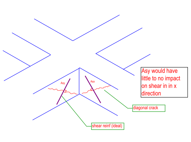
In theory, the shear reinforcement would run perpendicular to the diagonal crac. If you consider the strip running in the opposite direction, its diagonal crack also runs in the opposite direction per the sketch below. Therefore, the shear reinforcement for each strip needs to be designed to resist the shear in that particular strip.

Slab_shear3_ge0fgl.png
 
OP said:
In theory, the shear reinforcement would run perpendicular to the diagonal crac.

That may be the optimal way to orient reinforcement but it's not the only way. In modern times, shear reinforcement is usually oriented transverse to the plane of the slab for reasons of constructability. As you can imagine, running two systems of opposing, orthogonal, diagonal shear ties/stirrups through a common area would be quite the rebar placement nightmare.

Are you reinforcing a new slab or an existing one? I'd assumed that it was a new build slab right up until you showed your diagram of the diagonal shear reinforcing. Nowadays, I only see the diagonal reinforcing in existing slabs in strengthening applications.
 
DaveAtkins said:
My experience is using shear reinforcement in a slab is not cost effective. It is better to make the slab thicker.

Hokie66 said:
Agree with DaveAtkins. Slabs should not require shear reinforcement.

I feel that those statements require qualification.

I agree that it is generally uneconomical for slabs to have one-way shear reinforcement (Wall / beam support).

Conversely, I would argue that, nowadays, punching shear reinforcement in the form of stud rails has become almost a requirement for an economical, column supported slab design. This is because flat soffit formwork and thin slabs are two of the most important aspects of economical elevated slab construction (condos etc). So drop panels, column capitals, and even beams are rapidly becoming extinct.

Stud rail procurement and installation is pretty cheap in the grand scheme of things. The only times that I've seen stud rails negatively effect economy is when there are lead time issues in procuring the rails. And that's more of a construction management issue than an engineering one.

One may object to punching shear reinforcement from a reliability perspective of course. But, then, that is a different conversation.

 
A different conversation? In my mind, reliability is paramount.
 
hokie said:
A different conversation? In my mind, reliability is paramount.

Then perhaps your original comment ought to have made specific reference to reliability. DaveAtkins made specific reference to economy only. And that's what you seconded without making any reference to reliability. I specifically brought up reliability precisely because I suspected that was the unstated impetus for your comment.
 
hokie66 said:
In my mind, reliability is paramount.

This has me thinking some thoughts that I've not revisited in while.

Just why do we feel that a thicker slab is more reliable than a thinner, shear reinforced slab?

Consider:

1) Properly proportioned and and detailed, a shear reinforced slab ought to have a more ductile, forgiving shear resistance mechanism than a thicker, unreinforced slab. Not many engineers would prefer a deeper, stirrupless beam.

2) The "discovery" of size effects that tend to offset the benefit of thicker slabs kind of points the other way.

In a vague sort of way, I feel that the shear performance of thicker slabs may benefit from those slabs having less curvature at the supports, all other things being equal. That said, I can't point to any research confirming that. There is, of course, research pointing to the need for properly designed top steel to compliment stud rails. But we tend to that more carefully nowadays.
 
Since the subject of stud rails has entered the discussion, I wonder if much research has been done since this thread. Surely some of the early concerns have been addressed by now, and hopefully not just by the manufacturers.

thread507-306324
 
Kootk said:
Just why do we feel that a thicker slab is more reliable than a thinner, shear reinforced slab?

Nothing beats cubic inches.
 
Tomfh said:
Nothing beats cubic inches.

Great. Based on what fundamental logic / research? Seriously. Why does nothing beat cubic inches?

Is this not true in your experience?

KootK said:
Not many engineers would prefer a deeper, stirrupless beam.
 
hokie said:
I wonder if much research has been done since this thread. Surely some of the early concerns have been addressed by now, and hopefully not just by the manufacturers.

Yes, there are new code provisions that now have us provide properly designed flexural reinforcement to complement the shear reinforcement. Whether or not the research was sponsored by the stud rail people, I couldn't say.

I believe that a good chunk of the research was done under the guidance of James K Wight at the University of Michigan. That would be high credibility research in my book, regardless of the sponsorship.
 
Kootk said:
Great. Based on what fundamental logic / research? Seriously. Why does nothing beat cubic inches?

I just mean in terms of basic reliability. Shear studs and shear ties can work effectively if designed and installed correctly. I’ve just seen too many poor examples. Studs not extending all the way to the column, meaning the worst crack isn't even intercepted. Shear ties leaning the wrong way (away from column). Etc.

You're right that a deep stirrupness beam isn't great. Beams though have a relatively small amount of concrete, and the shear loading is all eccentric and unconfined at the supports. You don't get that balanced conical strut and tie effect you get with columns supporting a thick slab.
 
@Rapt @KootK, I value your opinions, what do you say to additive or non-additive steel reinforcing at overlapping one way slab strips?

Ignore punching, ignore concrete thickness, your slab needs one way shear reinforcing at overlapping orthogonal strips, do you add the reinforcing or do you pick the worst of the two?

S&T
 
KootK said:
Great. Based on what fundamental logic / research? Seriously. Why does nothing beat cubic inches?

For more personally, I prefer to rely less on the competence of the installer where possible. A bar being off by X number of mm becomes less of a percentage/relative difference in a deeper section, etc.

I don't really worry about this too much for 1-way shear and wouldn't arbitrarily deepen a section (beams tend not to have issues when it comes to installation in my experience) but it's not so forgiving with punching scenarios and I'd not like to rely on dense reinforcement spacings.

----------------------------------------------------------------------

Why yes, I do in fact have no idea what I'm talking about
 
Here is why I struggle with the FEM results and end up finding myself in the "double counting the load" camp...
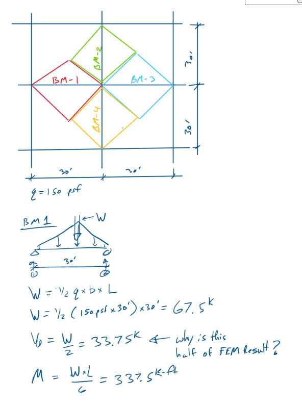
If I stay with SticksandTriangles example and I were to look break up the slab into four beams along the column lines and design for tributary load. I would get 1/2 the shear that I get from the FEM model, why is this? See example below:

Double_Counting_Load_dxusyl.jpg
 
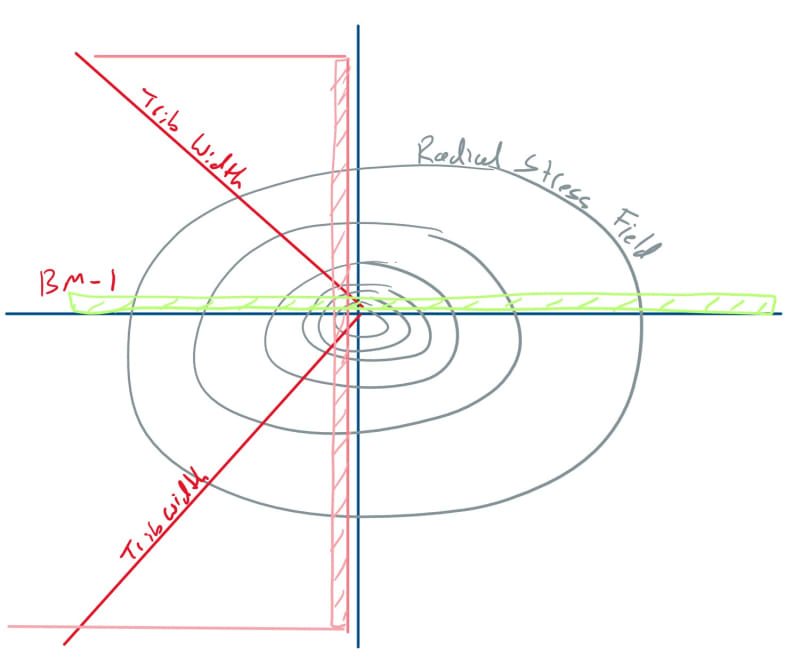
After some outside consultation, I suppose this is "why" they are not the same...
The strips are overlapping and essentially integrating the same stresses over the same areas (see image below). So it is "double counting" in my mind, but what should the required area of steel actually be? The SRSS argument above seems to have some legs here.


Double_Counting_Load_2_nkdhdk.jpg
 
In response to the discussion on punching shear, the biggest problem we see is the frequent condition where columns are poured too high such that they penetrate into the underside of the slab. This can significantly reduce punching shear strength.

Example: If a column is poured 2” too high and encroaches into an 8” slab, the punching shear strength will now be that of a 6” slab – and there’s a high probability that the 2 bars each way bottom integrity reinforcing through the column will not be installed through the column (because the top of the column is too high).

It is for this reason that we always like to perform a site visit prior to the first slab pour to point things like this out to the contractor, inspector, and rodsetter foreman.
 
Status
Not open for further replies.

Part and Inventory Search

Sponsor