Continue to Site

Eng-Tips is the largest engineering community on the Internet

Intelligent Work Forums for Engineering Professionals

  • Congratulations KootK on being selected by the Eng-Tips community for having the most helpful posts in the forums last week. Way to Go!

Shear Stress on Composite Beam (Divinycell + CFRP) 1

Status
Not open for further replies.

gui1993ac

New member
Sep 16, 2015
8
Hello to all!

This is my first post here.
Im designing a main wing spar where a Divinycell rectangular core will be laminated with 90 degrees carbon fiber on the four sides, to make a home building easier and possible.
In order to do so, I started with a analytical beam model that supports the aerodynamic diatribution. Im facing problems on the calculation of the shear stress, since the max shear stress (on the neutral beam axis) happens on a section that has 3mm carbon fiber on the sides and a 150mm width Divinycell core. I suppose the core will resist most of shear stress, but im not sure on how to calculate the shear stress on this composite section. My first assumption was that the core should resist alone to all of the shear stress, since in the carbon fiber on this orientation, will have very poor shear properties. But im not quite sure if this is a good assumption, or if thr carbon fiber will be sure to resist the stresses if i consider only the core. Since this is a preliminary model that will be later calculated in CAE software, any good enough aproximations for a simple design can be used by now.

Any insights on that would be greatly appreciatted!

Best Regards,

Guilherme
 
Replies continue below

Recommended for you

I sure hope your carbon fibers are running the length of the spar. Are you using tape or fabric? Relying on the core to carry shear in a spar dies not sound like a good idea. Better to have +/-45 fibers on the web sides.
 
Having fibers in 45° on the web was my first idea, so shear stresses would become only normal stresses to the fiber, but wouldn't it be a problem on the web section close to the edges, where the normal stresses due to bending moment will apply forces 45° to the fiber direction?

Could you give me any other insights on why relying on the core to carry shear is not a good idea?

Thank you for the reply SWComposites!

EDIT: I'm probably using carbon fiber fabric. Fibers are, at least on the top and bottom of the spar aligned with the span to resist normal stresses from bending moment.
 
Because i suspect that the shear loads on the spar are much more than the core can carry. And further, core is likely to be more susceptable to impact damage and environmental degradation.
 
Back in the eighties we used Rohacell foam as core in some TE structures. We almost ignored the core structurally (the core was there mainly as a support for bonding in production but it stabilized the skins for overall buckling and we still checked for local skin buckling on the foam, but all the applied shear forces were analysed as being carried by the skins, which were very curved so there were plenty of fibers in line with the shear loads).

Even with decent foam one ply of woven carbon 0.01" thick at 45° is worth about 4" of foam for the same shear stiffness. And that's dry foam at room temperature...oddly enough the ratio is lower for shear strength, about 80 or 100 instead of ~400.

[I think: woven carbon at 45°, G about 30000 MPa, shear strength about 440 MPa, 12 lb (heavy!) Divinycell foam, G about 80 MPa shear strength about 3.5 MPa.]
 
Hi,

although your final application is not clear ( rc model, homebuilt airplane,...??) , SWcomposites's advice holds in general.
Your spar web will be loaded in shear ( then +-45° fabric) and spar caps ( located where..?) will be loaded in tension/ compression.

It's is good practice ( conservative if you are building an homebuilt airplane) to consider loaded in shear the skins only, while the core's role is to help skins in resisting shear buckling. Beside, shear strenght of foam varies with density, then also an appropriate choice of such value should be done if weight is a main issue ( and it is in the case of an homebuilt aircraft).

RPstress's advice about Rohacell is also correct, but price plays a big role in this case ( Rohacell more expensive than a foam of same density ) .For small aircraft, density range of foam 55-70 kg/m3 is typical ( with 70 kg/ m3 you are close to the characteristics of Rohacell with rho= 48 kg/m3 ...then tradeoff price/performance).

About the values RPstress lists at the end for skins, they are commonly used in light aircraft design of shear loaded components.
 
Rohacell (a PMI) is the best core for specific properties and temperature resistance (it'll take 180°C and can be used when curing carbon/epoxy—and their latest grade says that's good for 220°C). As cpinz says, you pay for this—a slab 2.5 m by 1.25 m by 25 mm thick was about €500 last time we bought any (a few years back). Honeycomb (5052, 5056 or Kevlar) remains best for specific properties as long as in-plane properties don't matter. Only a bit lower specific properties are for balsa, which is better than all the foams (if you can put up with its environmental resistance and intrinsically high density: the lightest available seems to be 6 pcf (100 kg/m[sup]3[/sup])).

Note that dense foams and honeycombs have better specific properties than less dense ones. Since you usually want skins spaced well apart by a core this is more of a nuisance than something you can take advantage of.

Where carbon/polymer is about 8 or 15 times denser than foam but is at least 100 times stronger and 400 times stiffer it makes sense only to use foam to stop carbon buckling or if your production process needs it for some reason. Plus some people have an irrational hatred of foams.

Sandwich panels are the best use for even the best core.

It's worth noting that all boats are built with sandwich panels even for the hull (subject to many impacts including floating logs, etc., plus wave slamming loads) and usually the core is foam.

Your core at 150 mm thick is probably just about weight effective for stabilizing the carbon but it is a bit thick for that (on the other hand wasted foam doesn't weigh much). Finding a way to get the carbon panels closer together than 150 mm would be a little bit more efficient. But, usually you want the panels well apart and then it's just a matter of using the lightest core available that won't let the skins fail by local instability for the skin thickness you need. At 3 mm your skins are pretty thick. I'd be surprised if a 3 lb/50 kg core wasn't adequate.
 
This is for a homebuilt im planning on, still on the preliminary design by now, and this is my first composite spar design.

SWComposites,

Actually considering only the core i could find a Divinycell that can support the stresses, but after a analysis and comparing with 45° fibers on the web, i realized that would be very weight uneffective. I have now modelled the beam supposing two materials with different properties (Carbon at 0 / 90° and carbon at 45°), and it really seems the best option.

RPstress,

I've now changed my design to 45° fibers on the web and im now ignoring the core structurally.
I'm from Brazil and i'll look for this Rohacell (had never heard of it). I know a supplier here for Divvinycell, and will look to compare it with the Rohacell.

I'm still making comparisons for my spar as a 'I' spar (with Divinycell filling the 'I' spaces between the caps, to prevent web buckling) and a full core with carbon around it. The 3mm thickness in the webs i said before was still a preliminary design, since i hadn't really evaluated stresses on it by that time. Now i can see that can be reduced, but i still fear buckling there. I suppose the 'I' spar with foam filling the empty spaces will hold buckling better than the one with carbon on the outsides.

Even then, i suppose there is still a limit of how thin i can make my webs (besides stress), as the foam may no be able to hold buckling forever. Any tips on that?

By the way, do you know whats the usual range of carbon web thickness on regular homebuilts?

cpinz,

I'm now in this design you suggested, my only doubt is on calculating the web minimum thickness that the core can hold the buckling (if there is this limit), as i stated on my answer to RPstress above. Of course, since this will be a homebuilt, i plan on having a little more carbon there to account for calculation simplifications and other stuff...
 
Since this is for a homebuilt aircraft, your analysis should be very conservative and take into account the quality of the laminate resulting from the average person producing this spar structure in their garage. The concept of laying up carbon over a rectangular foam core seems like a good idea even though it would be heavier, since it would be easy for the average homebuilder to get right. Laying up and interweaving unidirectional and bias plies in an I-beam spar structure would be far more difficult to get right.
 
For a one-seat homebuilt, designed according to EAA,ASTM-LSA, BCAR, or LTF rules ( I strongly suggest you to take a look at them..), you will find that a conservative design ( from shear strenght viewpoint at ultimate load) for shear web of a wing supposed cantilever type, will give you 4 layers of plain/twill carbon fiber oriented a +-45° . As Tbuenlna correclty says, forget the use od UD tapes; there is no reason to use them unless your process is so valid to avoid any void beteween layers and so potential delaminations during fabrication. Woven fabrics work better from the maunfacturing viewpoint...besides you are not at risk to produce an unsymmetrical shear web because you confused the angles of lamination for both faces of the web ( easy when you are dealing with UD).

Nevertheless you will be requested to check for shear buckling...so check the strenght at U.L., check the buckling load...take the worst of two and use it to drive your final design. At the end you have two solution:

1) solid laminate shear web that satisfy strenght and buckling at U.L. ( I think that you will not be allowed to take L.L. for buckling check ....ask for it to certification agencies...in Europe for an LTF type certificate I was asked to verify buckling at U.L. for any element of the aircraft)---> more layers --> more weight---> easier to manufacture
2) sandwich structure ---> fewer layers ----> lighter ----> but is necessary a core ( the values of density given above are "good" numbers..[wink]..with the minimum value problably more closed to your needs )---> requires more attention in manufacturing.
About shear buckling calculation of solid laminated and/or sandwich you have methods form literature considered valid at certification level...then thake a look at them for your calculation..finite element method is not valid as unique way to certify a structure, because ,as rules say , your approach should be the " ...certification by analysis supported by test evidence.." , so the tests will give ok or not to you design.
Classical methods are the right choice for a project like your .

Hope this helps

 
Divinycell is about 2/3 as weight efficient as Rohacell so there's not much in it (so it may in theory need to be about 1/3 denser for a given duty). Pick whatever core will support your planned manufacture process and is available (I assume it's a pretty low temp cure and vacuum only). If we're messing about saving 1/100ths of pound here and there core type can make a difference, or if we're using a 180°C cure and autoclave pressure marine cores can be problematic. NB: Rohacell is pretty friable so it's easy to damage it in manufacture (the more recent 'Hero' (high elongation) grades have about 10% strain to failure and aren't so bad as the older WF grades, which were always getting damaged—a marine core may well be a lot easier to manufacture with; Divinycell seems to have about 25% strain to failure).

If you're using the core in a sandwich (i.e., to stabilize the skins for overall buckling) you must check for local instability: skin wrinkling and shear crimping. See NASA CR 1457 "Manual For Structural Stability Analysis of Sandwich Plates and Shells". Just Google for it and you should find a download (it's 10 Mb). The Shell Analysis Manual (NASA CR 912) is also very useful (24 Mb). The core modulus becomes very important for local instability.
 
tbuelna,

This is my first composite design, so being conservative is sure a must, and ill be sure to account for those building concerns, Thanks!

cpinz,

I'll take a nice read at those rules.
I'm sorry, but i suppose L.L. and U.L. you mean Lower layer and Upper layer, right?
I'ill be sticking with the sandwich structure, and for that im reading the NASA CR 1457 manual RPstress suggested there, and after a good read on the failures described on the manual, i still have some doubts on that, if i got it right.

Here it goes:

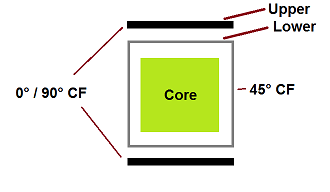
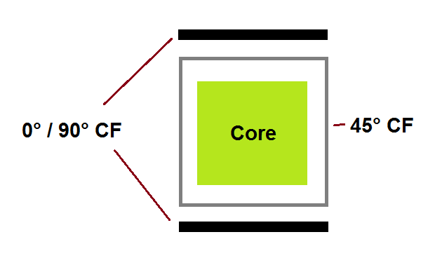
An exploded view of my current idea and design:
spar_design_l2bmzk.png


My design on 150% design load is giving me about 500MPa on the spar caps (0°/90°) and 59MPa on the lower caps, that are on 45° since they are the same fabric that continues from the webs (and can hold about 110MPa of stress on this direction). Max shear stress on the webs (that are now with 1mm each side) is 166MPa, then ok.

My doubts are:

FOR SHEAR CRIMPLE: I used the following formula for maximum shear crimp stress, that in the NASA CR-1457:

formula_bsiiga.png


This gives me about 650MPa shear crimping stress on my design. Considering a Divinycell with G = 28MPa

Since i have the lower caps at 45° in direct bonding with the core holding 59MPa and the upper caps over those holding about 500MPa, which of those should i compare to the maximum shear crimping stress?

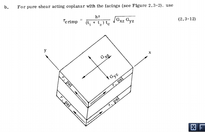
Also, the CR-1457 suggests a formula for pure shear acting coplanar with the caps:
pure_shear_hse50e.png


After reading through the whole text, i suppose that can be used to check the webs for shear crimping, but that gives me a very thin carbon web, less than 1mm on each side. Is my use of the formulation correct?

FOR WRINKLING: I also read the manual and used the formula shown there. Those gave me 273MPa max stress on the upper caps (that is too low compared to my actual 500MPa) and 171MPa on the lower caps (that are on 59MPa by now). Am i doing something wrong here or my design needs to be reviewed somehow.

Sorry about the long post, but as i said, this is my first composite design and many doubts are coming up.

Also, thanks again all you who spent some time helping me by now!

Best Regards,

Guilherme
 
L.L = limit load
U.L. = ultimate load = 1.5*L.L
For composite construction additional safety factors must be taken in account based on surfaces color, and in case of static tests executed or not at high temperature. Therefore 150% could not be the ultimte load.

It sounds strange that upper and lower spar caps have so different stress values; if you consider the spar as a built-in beam loaded in bending, upper and lower caps should have same stress in absolute value. Final laminate could differ if based on different allowables in tension and compression for carbon fiber, but the stress values derived from calculation should be equal...or not ?

What are the 90° fiber in the caps for ?
 
cpinz,

About what would be the limit load, i plan on using 150% on the loads and 150% to 200% on the material for Ultimate stress calculations.

The properties i got for standard CF are:
Young Modulus on the fiber direction: 70GPa
Young Modulus on loading at 45° with fibers: 17GPa

Those different stresses came up from modelling it as a built up beam, from those diferent Young Modulus in the two directions.

The 90° fibers on the caps are there because i designed it using standard CF fabric, which has fibers in those two directions (0° / 90°) instead of unidirectional fibers. Sorry if my drawing and explanation was a little confusing.

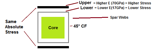
EDIT: Just to avoid misunderstanding, by lower caps I mean the 45° fibers on the tops, and upper caps the aligned CF that goes on just above it. I'm considering that the upper and lower sides of my whole spar will have the same CF thickness of both 45° and aligned CF. I think it might have got confusing by choosing those words to describe it.

spar_exp_l5mmum.png
 
Maybe I will misunderstand again, but are you saying that the caps ( that is the section of the beam wich resists tension and compression), are made with woven fabric oriented at 0/90 along the spar axis ?

The fact that you have different moduli in two direction doesn't explain why the cap's stresses ( I mean sigma_ tension and sigma_compression ) must be different. The beam you are showing is symmetrical ( geometrically and from material viewpoint ) about two orthogonal planes passing trough the center of the beam, then I would expect a symmetrical ( in absolute value) behaviour in terms of stresses ( sigma) in the upper and lower laminates.

Just to know....which are the dimensions of the spar ?
 
Yes, using CF just like this image, some fibers will be aligned and some will be at 90°

1952-50.jpg


The beam neutral line is in the middle of the spar, and stresses are symmetrical on the top and bottom of the beam. The stresses are different on the two "layers" of CF on each spar cap (upper and lower). On the upper caps, the carbon fiber aligned will hold more stress than the 45°. I hope a drawing will make what im trying to say clearer:

spar_exp_ohywa2.png


That's the final formulas that come from the two material beam, that im using:

stresses_nun2cz.png


EDIT: The spar is a 7m, that is 210mm height and 150mm width on the root and goes linearly to 100mm and 80mm width on the tips. I just noted in my posts i didn't noted that this is a homebuilt aerobatic aircraft, so stresses are higher on the spar than regular aircraft. Sorry for not saying it before, i skipped it on my previous posts.
 
I think that the use of ud tape for caps is more appropriate than fabric. Uni- has no kinks as happens with warp and weft of fabric, so more alligned fiber, better fiber volume fraction and higher strenght.

The value of E1=70 GPa that you cite, if referred to fabrics , seems too high. Anyway elastic moduli are not enough for a complete stress analysis...you will need some other properties to check the margins of safety. Be careful in choosing properties that will consider your manufacturing process.( Values too high or too optimistic could be rejected by a certification agency, in case you are pursuing a type certificate )
 
UD fibers can be used, no problem at all. But wasn't it noted before that could be issues eith manufacturing on homebuilts with UD?

Also, 70GPa is for the laminated of the CF.
Since i modelled my beam with different materials and i'm able to obtain the normal and shear stresses on my spar, what other parameters would be required to analyze? I cannot think of any other parameters (besides structural instabilities that i'm still trying to analyze, and probably fatigue). By saying elastic module is not enough for a complete stress analysis, do you mean having a bigger safety margin to account for my assumed material properties?

Thanks,

Guilherme
 
It was noted that it's difficult ( referred to DIY structures of course... not for a commercial aircraft where it's common) to layup UD in the shear web... not in spar caps, where it would be preferable ( for the reasons explained above).

Also for homebuilts to check for buckling is mandatory, not for fatigue ( in the sense that for such application where sound engineering judgement is used, carbon fiber is allowed to be considered fatigue resistant )

For " other properties.." I mean E11,E22,G12,vu12, sigma_allow_tension/compression, tau_allow,....in order to calculate your Margins of Safety or Reserve Factors or whatever you need to comply with the requiremets of a safe structure .
From your previous post: " My design on 150% design load is giving me about 500MPa on the spar caps (0°/90°)...." what does it mean in terms of Margin of Safety ? Nothing unless you have strenght allowables to compare with...to be honest with such value of 500 MPa and supposing hand lamination with vacuum bagging, I think you are just outside of the allowable for compression in a carbon fiber cloth.

My suggestion: if you really want design your own airplane, submit your calculation to an expert who can advice you in a more appropriate way, expecially in the field of composites ( better if he/she has experience with manufacturing). Even if you are talking of an homebuilt, you are always talking of an aircraft...for these reasons airwortihness rules exist also for small airplanes [smile]

Cpinz
 
cpinz,

I'll be sure to get my calculations revised by an expert. I'm trying to get in touch with people that already designed aircraft with carbon spars here in Brazil, by now just trying to learn and do most of calculations i can in ways of getting a starting point for dimensions.

Also, i'll sure get better CF laminated properties for the complete design. By now, my calculations are based on generic data, and that needs to be changed. I think to proceed now i really need an expert help.

Thank you for all the help cpinz! If i get any advances i'll be posting it here!
 
Status
Not open for further replies.

Part and Inventory Search

Sponsor