Nereth1
Mechanical
- Feb 2, 2014
- 136
Hi all,
This comes from a mech eng trying to understand a structural engineering calc and why it contrasts so hard with mech engineering calcs. Typically when I analyse a bolt in a hole near the edge of a steel plate, based on sources such as Rourkes, Shigley's, and Machinery's handbook;
Mechanical practice - Bearing of the bolt against the hole edge:
Plate yield point = [bolt diameter]*[plate thickness]*[tensile yield limit]. Obviously a small amount of yielding will be required before this as well for the purposes of the bolt getting full contact with the hole edge.
Mechanical practice - shear tearout of the plate:
Plate yield point = [edge distance]*[plate thickness]*[2 shear planes]*[0.577*tensile yield].
By contrast when I look at AS4100-Steel structures:
Structural practice - Bearing of the bolt against the hole edge:
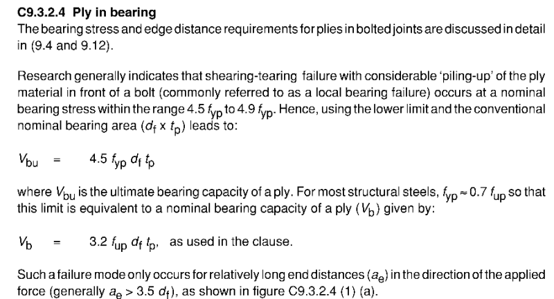
Bearing ply capacity = [0.8 capacity factor]*[3.2]*[bolt diameter]*[plate thickness]*[tensile strength]
I understand designing around ultimate strength rather than yield (structural engineering seems to be pretty plastic-deformation accepting in general). What I don't understand at all is the 3.2 factor. I can only speculate this is included as some kind of respect for triaxial stress states from compression of the bolt head, but not all bolts are tightened down particularly hard, no specific requirement for tightness is made, and even so, 3.2 seems like a massively excessive factor even for that. To me, by definition a ductile material (i.e. steel) has failed at 1*bolt diameter*plate thickness*tensile strength, if not, your tensile strength is wrong. I would really like that 3.2 factor explained to me.
Structural practice - shear tearout of the plate:
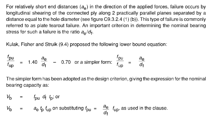
Tearout ply capacity = [0.8 capacity factor]*[thickness of ply]*[tensile strength of ply]*[edge distance]
- They are using tensile instead of shear properties - this I don't understand unless it relates to the next point
- They use a single shear plane - or perhaps they are just analysing for the plate 'popping' apart in a tensile manner?
- They are using ultimate rather than yield strengths (this I assume is just the general acceptance of yielding in a lot of structural engineering)


