Continue to Site

Eng-Tips is the largest engineering community on the Internet

Intelligent Work Forums for Engineering Professionals

  • Congratulations KootK on being selected by the Eng-Tips community for having the most helpful posts in the forums last week. Way to Go!

Shear Wall Design

Status
Not open for further replies.

Zouatine

Structural
Mar 18, 2020
36
Respected All,
Hope you are doing well,

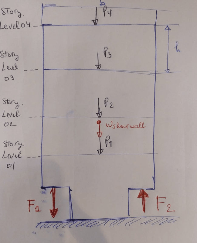
I wanted to design a shear wall which has a springs at its base , However for the sake of the simplicity, I just extract the highest force which may the springs apply on the shear wall , the next figure shows the FBD of the shear wall :
Shear_Wall_jghtaf.png


Where,

P1,P2,P3,P4: are the gravity load carried by the shear wall coming from the slab.
Wshearwall: Self Weight of the shear wall.
F1 and F2 : are the forces applied by the springs where the F1 is the tension force and F2 is a compression force.

For the design of the conventional shear wall, I was extracting the forces (P,V,M) acting on each story level (by using the option in sap2000 'Section cut-out') and carry out a hand calculation to design the shear wall.

Since I have two concentrated forces at the base ( F1 and F2 ) in addition to the gravity load . Would you please help with your thoughts on how can I carry a hand calculation to design this shear wall ? or any exp which could be helpful.

Thank You,
 
Replies continue below

Recommended for you

Need more info as to the nature of the springs. Why do they exist? Are these dampers of some kind for a low damage solution? Or is the architect just a nutter?
 
What I can see is the portion with reduced width at the base requires attention. Which can be treated as a cantilever column with gravity load on the center and a moment (due to F1 & F2) acting.
 
I would also question the spring concept. You could model a compression spring depending on your soil and foundation design, but what structural element are you envisioning to act as a tension spring? These are locations of hold downs and I have not seen them designed as springs. Do you really have cut outs in the shearwall as shown? That may require some fancy detailing to resolve stress concentrations.
 
Dear Mr Greenalleycat,

Thank you for your kind reply, the spring is called a ring spring , this device is installed in the structure to provide a self-centering when earthquake load will occur, this spring element will dissipate 60 % of the applied load (Earthquake Energy) through the friction between the rings.I performed the Pushover analysis to determine the limit point where the spring will broke ( failure) .at that point the spring in tension F1 will apply a load of 3600kN on the shear wall where the force in the other spring (F2) will reach 1900kN .

 
Without knowing the full scale of the project I am hesitant as it is clearly a complex and significant design.
My initial thoughts are that you could approach it using something like the method presented in this paper
(page 56 is where the relevant bit starts)

Apply your floor reactions at the appropriate locations and I guess you would have to manually apply your spring loads at the appropriate nodes
You should then be able to see a distribution of forces throughout the member which you can quantify steel against
I would give very significant consideration to how you will detail at the section step change though - that location is begging for some nasty cracks to form!
 
Dear MotorCity,

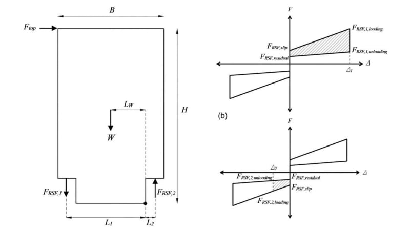
Yes the spring will be acting in tension when the lateral load will applied while the other one will in compression, Nevertheless, the two springs are already designed ,I'm left with reinforcement in the shear wall, I'm confused about the section that should resist the tension force as well as the distribution of the rebars. I just attached this picture for the clarification. we have the same concept except this Timber Wall, the two springs are acting in Tension and compression respectively , and on the right side can the full Hysteresis curve of the springs.

Springs_hllmxh.jpg
 
What is the anchorage of the springs into the shear wall?
That will give you a starting point for the reinforcement design

I would expect something like cast-in bars or rods running up the full height of the wall
Alternatively, could be some sort of post-tensioned system that casts in tubes into the wall then rams big bearing plates onto the top of the wall?
Those two methods would require different detailing as the force is applied in different ways
 
Status
Not open for further replies.

Part and Inventory Search

Sponsor