Continue to Site

Eng-Tips is the largest engineering community on the Internet

Intelligent Work Forums for Engineering Professionals

  • Congratulations KootK on being selected by the Eng-Tips community for having the most helpful posts in the forums last week. Way to Go!

Sheet pile wall design with soil springs 2

skewl

Structural
Jul 27, 2021
46
I want to preface by saying geotechnical engineering is not my forte.

I understand conventional design of steel sheet pile walls would utilize active pressure and passive pressure. At certain depth, the two sides would balance out. I would design the wall to that depth (or more to achieve higher factor of safety) and the wall section based on the moment generated.

However, I have a project where the geotechnical report has suggested due to the weak nature of the soil, I cannot consider passive pressure conventionally and need to model the interaction as soil-springs instead.

Based on the soil-spring parameters and the ultimate lateral resistance of the soil (100 kPa @ 1.4m width = 140 kN max), I find that I can never find the balance point between the soil-spring reaction and the active pressure if I take the active pressure all the way to the depth of the wall (Model A). The result I get under this modelling assumption is that I need to install toe pins at the bottom of the sheet pile, which I think is absurd given the 15+ m of embedment.

Thinking about this problem logically, burying a steel sheet pile wall underground with soil on each side should not generate any force on the sheet pile wall. Therefore, I remodeled my wall with the active pressure only applied on the cantilevered section (Model B). The results I now get is more inline with what I was expecting.
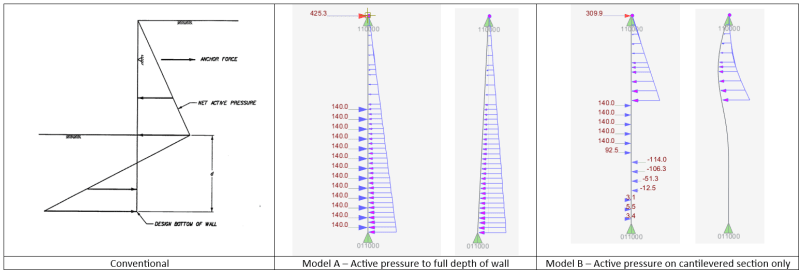
Screenshot_2024-10-18_184346_dqrnb1.png


So the question is, am I right in modelling it as Model B or am I still missing something?

Thanks in advance
 
Replies continue below

Recommended for you

It is correct to continue the active pressure on the retained soil side of the sheet pile. You say "Thinking about this problem logically, burying a steel sheet pile wall underground with soil on each side should not generate any force on the sheet pile wall." This is incorrect. Lateral earth pressure is a function of vertical earth pressure. There is greater vertical earth pressure on the retained side of the sheet pile than on the excavation side. The retained soil will surcharge the soil on the back of the sheet pile below the base of excavation. In competent soil, the imbalance of soil can be resolved with passive pressure and sufficient pile embedment. You, however, are not in competent soil.

If this was a soldier pile wall with discrete embedded piles, you could make the case that there would not be an active force acting on the embedded portion of the piles. Many will argue against this (and rightly so in some circumstances) as it is dependent on soil conditions, but the soil on the retained side may be able to arch around embedded pile toes. However, you are designing a continuous sheet pile wall. The soil cannot arch around the embedded sheet as the embedded portion is continuous.

I cannot comment authoritatively, as you have provided limited soil information, but this sounds like a case where the soil is sufficiently soft to put the embedded toe into a cantilever state. If that is the case, then at least two rows of bracing would be needed to maintain stability of the wall.

I should also point out that you appear to be using a pin at the base of your soil spring analysis model. I don't know what software you are using, but it would be incorrect to use a horizontal reaction boundary condition at the base of your model. This would be akin to having a brace or tieback at the very bottom of your sheet, which in a practical sense, is not feasible.

Forgive me if this sounds a little harsh. I hope it helps.
 
Thanks for the response MTSOE. It is great information and I did not find it harsh at all.

I do agree with what you are saying. I’ve only considered Model B after trying for a while to make Model A work. The other context I have not mentioned is that there was a recent steel sheet pile wall adjacent to the limit of our scope that has even less soil embedment with no toe pin. So, I became curious how they made that work.

Regarding the model. The pin at the bottom only provides Z and Y-axis restraint, not X-axis (horizontal) restraint as a tieback would provide.
 
skewl said:
However, I have a project where the geotechnical report has suggested due to the weak nature of the soil, I cannot consider passive pressure conventionally and need to model the interaction as soil-springs instead.
I would be interested in seeing a typical soil boring and the geotech report's recommended soil properties. What is the height of retained soil? Where is groundwater? Any surcharge loads behind the wall? Are you applying safety factor(s) to the soil properties or to the calculated embedment depth required for moment equilibrium?

 
I would be interested in seeing a typical soil boring and the geotech report's recommended soil properties. What is the height of retained soil? Where is groundwater? Any surcharge loads behind the wall? Are you applying safety factor(s) to the soil properties or to the calculated embedment depth required for moment equilibrium?

Sorry for the late response, I don't check the forum often.

Some more context of the site:
- The steel sheet pile wall (300m long) will be a permanent structure retaining an expressway from a river. There are existing steel sheet pile walls in place, but they have deteriorated. A section of the wall next to our wall(owned by a different owner) was rehabilitated ~2 years ago. We have design drawings for that new design but not their geotechnical information.
- The height of the retained soil is 6m at a critical location (but 95% of the wall are around 3m). I am also investigating the effect of a 3m scour (based on some discussions with local conservation authority), so let's say the retained height is around 6m. The total height from the top of the expressway to the bed rock is around 22m and the total height from the river bed to bed rock is around 16m.
- Some information from the geotechnical report:
Screenshot 2024-10-31 163022.png
report screencapture.png

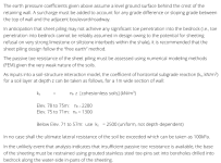
What I have interpreted from the 3rd paragraph is that we cannot rely on passive pressure coefficient and rather need to model the passive toe resistance as soil springs.

For now, I am simply exploring how to model to passive pressure side of the sheet pile wall. Live load surcharge and unbalanced water level condition will be explored later. However, based on what I have read, it seems that we need to auger down to install some toe pins (which I wanted to avoid).
 
Looking at this briefly, I would look at Model A and consider sheet piling with toe pins drilled into bedrock or a combi-wall of beams drilled into rock with sheets driven to rock. The toe pins or drilled-in combi-wall beams would provide passive resistance.
 

Part and Inventory Search

Sponsor