I want to preface by saying geotechnical engineering is not my forte.
I understand conventional design of steel sheet pile walls would utilize active pressure and passive pressure. At certain depth, the two sides would balance out. I would design the wall to that depth (or more to achieve higher factor of safety) and the wall section based on the moment generated.
However, I have a project where the geotechnical report has suggested due to the weak nature of the soil, I cannot consider passive pressure conventionally and need to model the interaction as soil-springs instead.
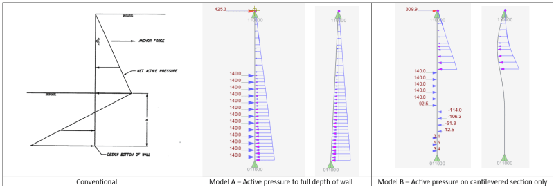
Based on the soil-spring parameters and the ultimate lateral resistance of the soil (100 kPa @ 1.4m width = 140 kN max), I find that I can never find the balance point between the soil-spring reaction and the active pressure if I take the active pressure all the way to the depth of the wall (Model A). The result I get under this modelling assumption is that I need to install toe pins at the bottom of the sheet pile, which I think is absurd given the 15+ m of embedment.
Thinking about this problem logically, burying a steel sheet pile wall underground with soil on each side should not generate any force on the sheet pile wall. Therefore, I remodeled my wall with the active pressure only applied on the cantilevered section (Model B). The results I now get is more inline with what I was expecting.
So the question is, am I right in modelling it as Model B or am I still missing something?
Thanks in advance
I understand conventional design of steel sheet pile walls would utilize active pressure and passive pressure. At certain depth, the two sides would balance out. I would design the wall to that depth (or more to achieve higher factor of safety) and the wall section based on the moment generated.
However, I have a project where the geotechnical report has suggested due to the weak nature of the soil, I cannot consider passive pressure conventionally and need to model the interaction as soil-springs instead.
Based on the soil-spring parameters and the ultimate lateral resistance of the soil (100 kPa @ 1.4m width = 140 kN max), I find that I can never find the balance point between the soil-spring reaction and the active pressure if I take the active pressure all the way to the depth of the wall (Model A). The result I get under this modelling assumption is that I need to install toe pins at the bottom of the sheet pile, which I think is absurd given the 15+ m of embedment.
Thinking about this problem logically, burying a steel sheet pile wall underground with soil on each side should not generate any force on the sheet pile wall. Therefore, I remodeled my wall with the active pressure only applied on the cantilevered section (Model B). The results I now get is more inline with what I was expecting.
So the question is, am I right in modelling it as Model B or am I still missing something?
Thanks in advance

