Eng-Tips is the largest engineering community on the Internet

Intelligent Work Forums for Engineering Professionals

Shoring Wall - Corner Brace Thrust Capacity

Status
Not open for further replies.

JSD1986

Structural
May 2, 2012
25
0
0
AU
Hi everyone,

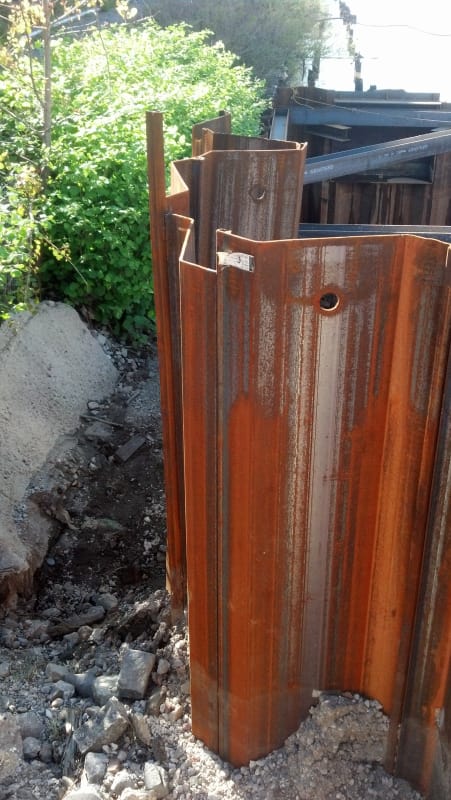
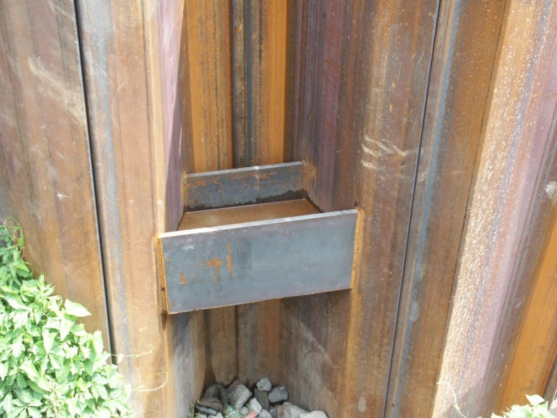
At the company I work for (design and construct shoring wall contractor) it is common to implement a corner brace for , say, a sheet pile wall.

cornerbrace_s1m6hc.png


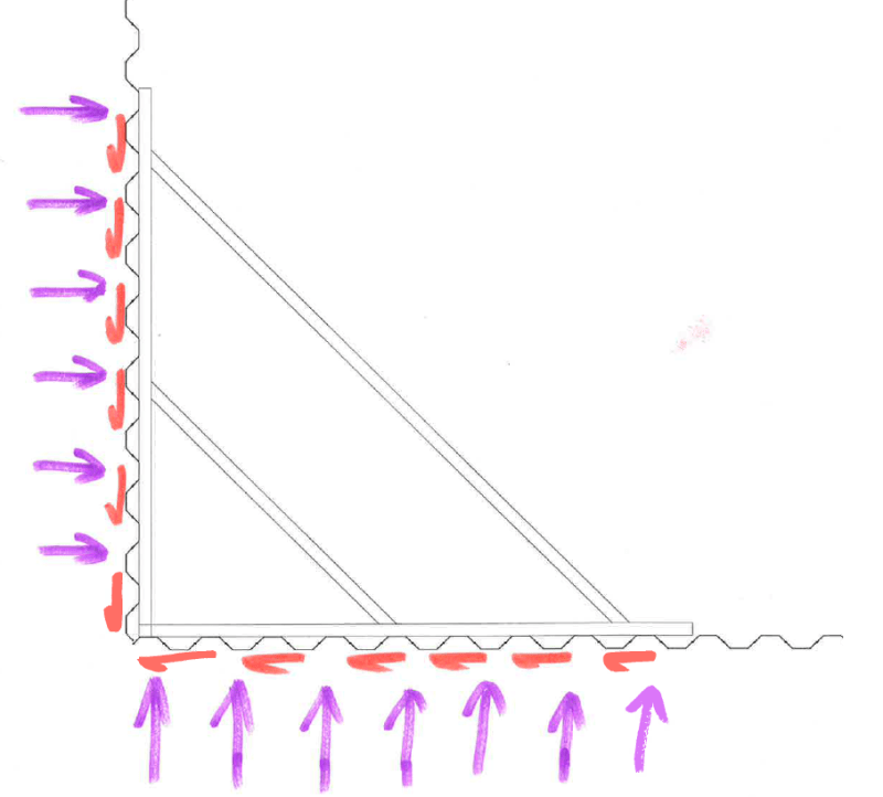
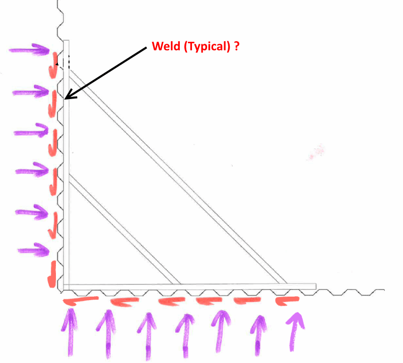
Analyzing the system in 2d is simple: prop forces, embedment, wall forces etc. However I cannot find any guidance on how to resolve the load transferred into the the 'shear wall'.

The more senior people designing this also have no idea either - just that "it cant fail like that".

Any ideas/comment?
 
Replies continue below

Recommended for you

I've designed many systems like this in the past. If the system is closed on all sides, then the thrust load can travel along the wale to the opposite set of corner braces then to the opposite wall.

The only time I've tried to analyze the loads in shear is when there hasn't been an opposite wall. In those cases I looked at the unit shear required along the shear wall and compared it to the shear strength of the soil. My goal was to determine how much soil area needed to be mobilized to withstand the shear load. In the cases I've looked at the required area was a small percentage of the "shear wall" area; so I considered the design acceptable.

Not saying the above method is perfect, the load path on the shear wall as you get away from the wale is certainly not as robust as you might like; but so far I haven't seen any problems.

Mike Lambert
 
Regarding your repeated comment: "it can't fail like that" --> Yes, of course it it can, given a high enough load magnitude.
However, for typical steel sheet piling, say PZ27 with 3/8 inch thick wall, the diaphragm shear strength is very high.
Very crudely, compare 18 gage metal deck (less than 1/16 inch thick) - say B deck, that has 2,000+ plf shear strength, then by extension can you not get an order of magnitude shear strength.
I think the shear strengths of light gage deck are ultimately based on full scale lab testing, not calculation.
If there is a recognized method of calculation for strength and deflection, I would be interested in reviewing it.
PEInc should weight in here.
 
I've had EOR demand calculations for this before. I was able to make it work using purely weak axis bending strength for soldier piles (HP section). I've never had to try it with sheets.


While there may be more than one way to look at this problem, I don't believe that there is a good or totally correct way. The key is to be conservative when figuring out how far to run bracing wales from the corner. I had a cofferdam where the wales needed to be terminated about 60' from the corner before transitioning to tieback anchors. The wales needed to be terminated because they would have interfered with abutting concrete walls with architectural finish. Unfortunately, the SSP squashed at the end of each wale, but just before the tiedback SSP began. The inserted photos show (but not well) the areas where the sheet pile doubles were squashed along the length of the walls. One photo shows how we needed to install some welded steel beams to prevent further squashing of the SSP. A similar situation was also a major contributing factor to a significant, braced, soldier beam wall collapse in Washington, DC back around 1990. Don't stop the wales too close to the corner.

IMG_20140505_084532_226_dxjw7l.jpg

PICT2287_f4c1vd.jpg


Geopavetraffic - yes when the wall is fully enclosed 'box' then yes not really an issue. I have looked at it the same way as you by working out the kpa required and using judgement to decide if the kpa is reasonable. - however still cannot find any literature on this.

SlideRuleEra - walers welded to the sheet piles.

ATSE - I might be reading this wrong, but are you talking about structural strengths here? What I'm talking about is the capacity for the soil to prevent shear sliding.

 
Guess that I don't understand the situation... just can't see a major problem.

If the wales are welded to the sheet piling, and the sheet piling is adequately driven to provide some cantilever support, why don't the welds distribute the axial wale load to each sheet? Embedment of the sheets would transfer the load to the soil. I would expect the average magnitude of this load on each sheet would be very low... would not be hard to calculate an approximate value.

cornerbrace_s1m6hc-3_sboiij.png


Fully agree with PEinc about maximizing wale length.

I will add a comment about the sheet pile corner... that detail is very important. If the proper (corner) sheets are used to make the corner continuous and the corner sheets used allow maximum support by both wales, the stability of a reasonable length of the wall, in both directions, will be improved. For high loads, just "butting" typical sheets together to be a corner, IMHO, is not good.

[idea]
[r2d2]
 
JSD - Yes, I answered a different question that what you asked. Just not paying attention. Your question is more difficult.
If you carried the walers / stiffeners horizontally all the way to the far side (full length), then the passive resistance (and/or at-rest soil demand) will resist (some of) the in-plane forces. That is, "around the corner" at the far end of the box, there is resistance normal to the applied load in question.
However, what is the interface shear strength between the fluted sheets and the soil, given the installation tolerances (potential semi-contact in the upper soils)? High variability, depending on soil type, depth, depth of flutes...
Temporary shoring works the vast majority of the time, but not always because we understand it.
 
Follow-up to my previous response: This link takes you to the OSHA report on the 1990 Washington, DC sheeting wall collapse. Page 48, Section 4.1.2 describes how the soldier beams were not capable of resisting the thrust that came along the walls from the perpendicular, end, sheeting wall. It is hard to accurately estimate (or easy to overestimate) the resistance of a sheeting wall when supporting an axially loaded wale. As I said previously, this was a contributing cause of failure, not the only cause.


SlideRuleEra -typical weld is 150mm weld top and bottom of waler to each sheet at 750ctrs, weld is 6mm continuous fillet weld. so each sheet pile is very well connected to the waler.

PEinc - yes found that doc - was a good read. ~15m cut depth failure is the stuff I have nightmares about.


If I had to calculate it, it would be like this.

wall_e1u9e6.png
 
JSD1986 - I see that the sheeting span from the wales to bottom of the excavation is 4 meters. With the sheeting being used, how much could that span be safely increased? In other words, locate the wales closer to top of the sheeting. If this is practical, would decrease wale load by increasing load on embedded portion of sheeting. Sheeting bending moment has to be considered, too.

[idea]
[r2d2]
 
SlideRuleEra - the above was just a random depiction - however by raising the brace level the brace load would be less but I believe creates more issue as the distance between the centroid of the shear resistance to the strut load increases and induces overturning to the whole system.
 
Status
Not open for further replies.
Back
Top