Continue to Site

Eng-Tips is the largest engineering community on the Internet

Intelligent Work Forums for Engineering Professionals

  • Congratulations KootK on being selected by the Eng-Tips community for having the most helpful posts in the forums last week. Way to Go!

Should I crack these transfer walls?

Status
Not open for further replies.

7788_011

Structural
Feb 7, 2022
24
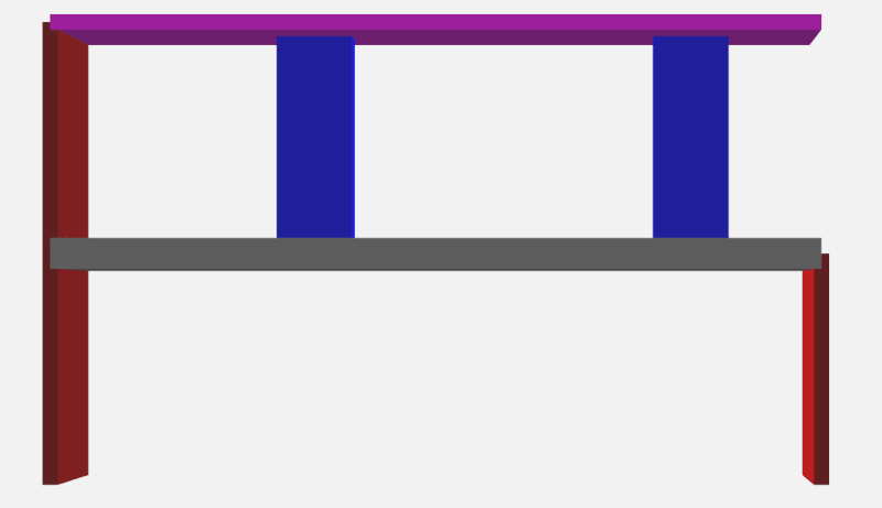
Below is a section of the transfer structure I am working on. The transfer slab is going to be 400mm PT.
model_qyahpo.png


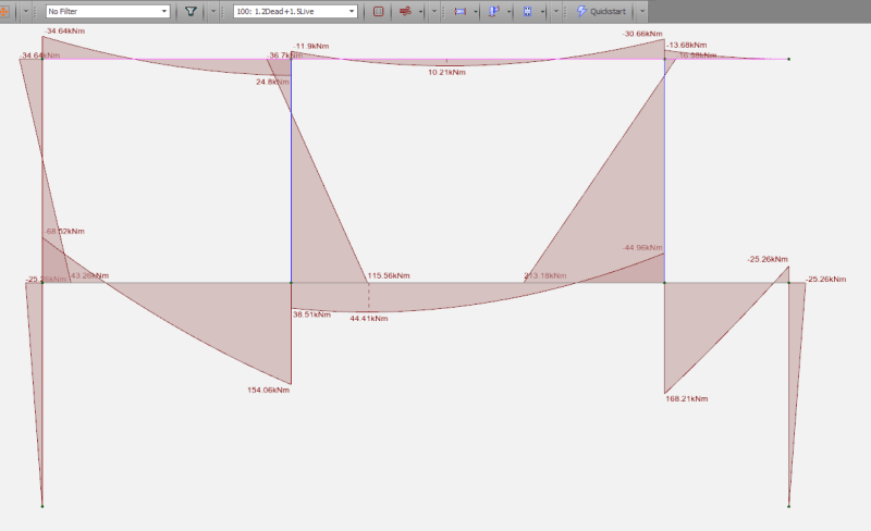
I am getting large moment at the bottom of internal transferring walls as you can see from the picture below.
22_elzhin.png


Above is a 2D model but I have created a full 3D model and considered the load construction sequence but still I am getting large bending moment under gravity, leading to heavily reinforced walls.
My question is, can I reduce the stiffness of these walls since these moments exceed their cracking moments?
 
Replies continue below

Recommended for you


What is the reason for the use of walls ? In this case I would try to use columns which is more flexible than wall .
 
The out-of-plane thickness is 200mm. I guess you can call a 200x1000mm either wall or column. But even if I reduce the wall to 200x600 the moment is still quite large
 

I am not sure if you checked with dimensions 200x600 the moment is still large . You did not mention for seismicity. If it is not seismic zone, you may design the column assuming gravity column and nominally hinged at the bottom.
 
For transferred elements design I typically create a save-as model which provides pinned supports at the transferred level. I would then design the transferred element for the loads from the pinned supports. Your structural model is creating some vierendel truss behaviors - and I would be concerned about the transfer element benefiting from that behavior.

EDIT -
Corrected that my primary concern here would be for the transfer element - not the transferred element.
 
If your program supports it, try using a stepped construction sequence. This will reduce Vierendeel behavior. This is a nonlinear analysis which gets closer to what we would expect with a hand calculation. Your current linear analysis is assuming that the whole structure is built in one shot. In reality, the transfer floor will be built first and allowed to deflect before building the stuff on top of it.

Edit: Also to answer the topic question of whether it should be cracked, those walls should definitely be cracked, regardless if you're considering them to be columns or not. Because these kinds of moments will cause the concrete to crack in tension. This will help reduce the moment without going so far as assuming that it's pinned.
 
It is a non-seismic zone. I can pin the column in the analysis but my concern is that in real world it will not follow this assumption - there will be moment at the ends of the columns. Can we ignore this moment and why?
Just to clarify that using vierendeel truss to design the transfer slab is not my purpose here. What I wanted to ask is if it is safe to reduce / ignore the end moments at walls when it comes to the design of these walls.
 
I did have run a 3D model analysis with staged construction sequence as I mentioned. It does reduce the moment but in some case the moment is still large.

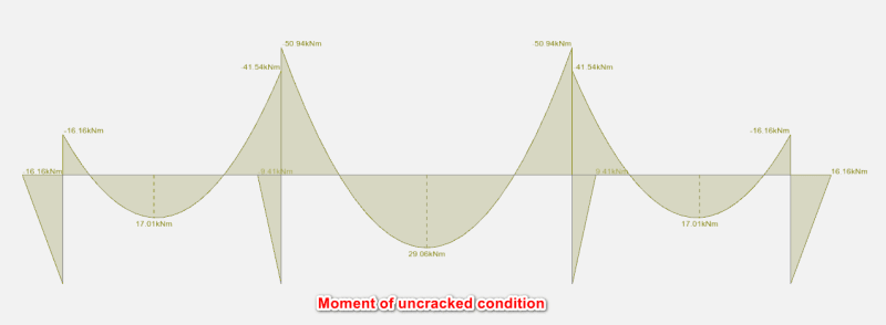
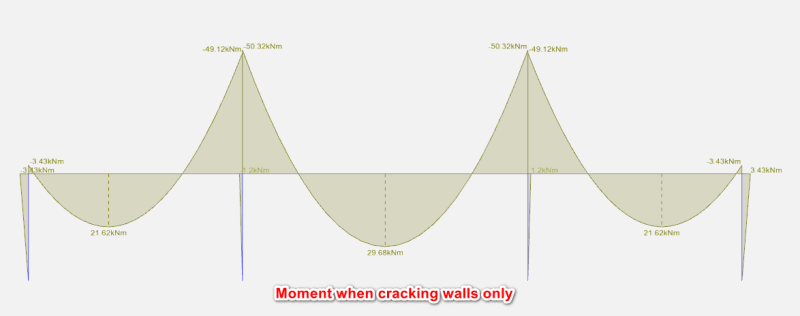
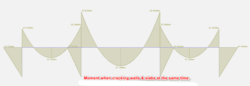
Yes reducing the stiffness of walls alone will reduce the moment but what if we crack the wall & slab at the same time? The moment might re-distribute back to the walls.
I have created a 2D frame to illustrate this.

111_bcxqk7.png

222_xulnsb.png

333_dgzfq0.png

444_nl6qfe.png
 
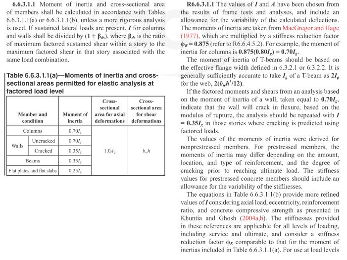
Normally the wall and slab stiffness are reduced based on the expected cracking. ACI recommends the below for a non-PT structure which could be used for a simple frame structure you show above, but it is not applicable for the 400mm thick PT transfer slab supporting 1.0m walls with minimal axial loads.


If you want to accurately calculate the flexural stress shared between the PT slab and the walls you may have to do a detailed second-order inelastic analysis taking into account the construction stage, creep, shrinkage, rebar...etc


However, if the structure is small and the expected cost saving is minimal, I would design the PT transfer slab assuming pinned walls and reinforce the walls for the full flexural load as shown in your frame analysis for uncracked walls.

Capture_n9dnru.jpg
 
Hetgen said:
I would design the PT transfer slab assuming pinned walls and reinforce the walls for the full flexural load as shown in your frame analysis for uncracked walls.

I would do this.

Regardless of what stiffnesses you assume and how you apportion the bending moment, it’s not right to waive the entire bending moment in the wall. It’s the stiffest element and the bending moment will go there.
 
The uncracked walls & slabs model from the very first picture is a simplified 2D model without considering construction sequences.
When you design your slab in this way, do you take the axial load of walls above from staged construction sequence?

If so, is it really safe to ignore the moment in slab since there will be quite large moment in slab at where walls are transferred in addition to axial load. (Understand the moment is from vierendeel truss but in real world there will be some vierendeel truss behaviour)
 
Personally I would pin the walls. I see that is SpaceGASS, wouldn't those walls be precast anyways? Seems the norm here in Australia. In which case you probably don't want to be trying to get a moment connection to work.
 

Yes it is. Walls are in-situ tho. Also, I don't think precast walls means pin connection especially in plane? The dowel bar will still give you moment to transfer.
 
Status
Not open for further replies.

Part and Inventory Search

Sponsor