I have three separate parts (shell element plates) coming together at the bottom where I get my warning message - here the bottom concrete deck, a rectangular and circular concrete part all meet and my FEA software doesnt seem to like it, can I still run this safely or should I try to model it some other way? I dont see anything off with forces and displacements when I run my load case.
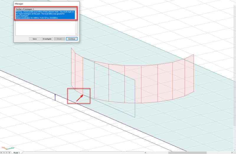
Warning: Unexecutable local refine of finite element mesh. Very small angle on the region/subregion at this point. The local refine was ignored for region/subregion.

Seen from birds view
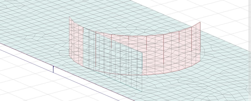
How the mesh looks, dont see anything too crazy?
Warning: Unexecutable local refine of finite element mesh. Very small angle on the region/subregion at this point. The local refine was ignored for region/subregion.
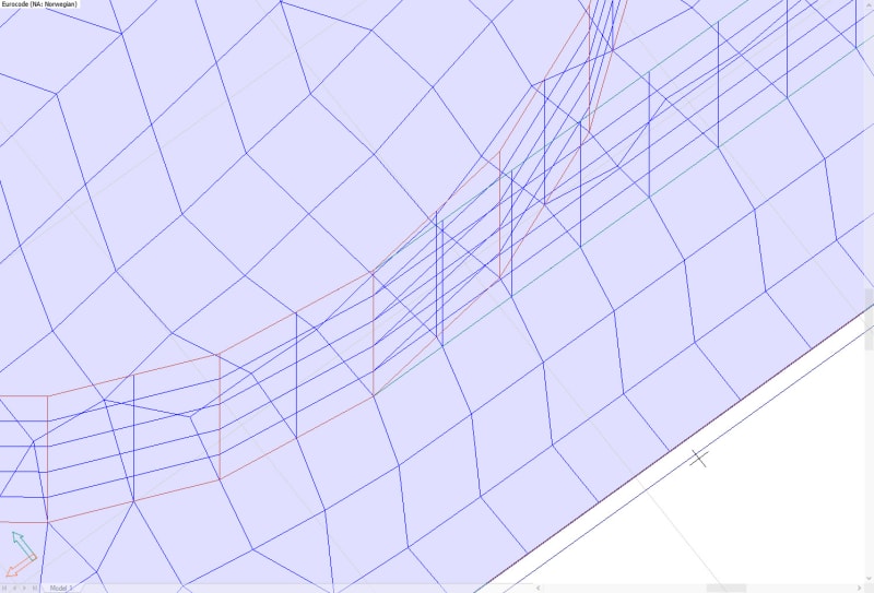
Seen from birds view
How the mesh looks, dont see anything too crazy?
![[smile]](/data/assets/smilies/smile.gif "[smile] [smile]") .
.