Continue to Site

Eng-Tips is the largest engineering community on the Internet

Intelligent Work Forums for Engineering Professionals

  • Congratulations KootK on being selected by the Eng-Tips community for having the most helpful posts in the forums last week. Way to Go!

Should it be HCF or LCF?

Status
Not open for further replies.

Lee.Conti

Automotive
Nov 8, 2019
87
I am required to check a fatigue life for a connector holding two parts under an acceleration in mini seconds. I wonder if this should be HCF?

I have done HCF and LCF for other product, call it A, but the load condition is different. Product A experiences Temperature, Pressure and Acceleration. For product A HCF, the acceleration is high inertial force, XX G.

Since the connector is under high G shock, I wonder if I should consider HCF? Is Goodman diagram the only approach for HCF? I only have experience using Goodman for HCF.

But, how do I construct the alternating stress? The connector is under random vibration as normal condition.

Thank you!
 
Replies continue below

Recommended for you

Another question... I have been doing LCF and HCF for the condition if the cycles less than 100K, it is LCF. HCF usually 10^8.

But from the textbook, LCF is for the cycles less than 1000 cycles ... so, it is dependent of the industry or product?
 
It is a little bit of a cyclical argument but generally as you mention, the "demarcation" in an engineering sense between HCF and LCF is somewhere on the order of 10^3 to 10^5 in terms of cycles to failure. Basically if you take a stress-life approach (using S-N data) and get an answer for total life in this range, you know you are probably being unconservative, and should favor a strain-life approach using strain controlled data.

I think the key is that fatigue failure is the result of damage accumulation - if you consider cyclic stress strain curves, there is a hysteresis in the response to load behavior which affects how the damage accumulates. If you have a situation where the operating stresses are a significant portion of the fatigue strength or even the yield strength, damage will accumulate more quickly. You have to remember that because of the hysteresis, the ORDER of the previous load magnitudes matters, not just the magnitudes themselves. In general high load = high strain. This is simply not represented by typical S-N data because those curves are produced with specimen which are stress-controlled.

A stress life approach is much easier to implement because S-N data us more readily available. I might start by performing this analysis and seeing what you get for a total life. If it is relatively low, then you might need to get more detailed.

What you need to do is define, in detail, the load vs time duty cycle for the part. This could include a fluctuating load spectrum. Then perform a stress life assessment which accounts for damage accumulation first. You say the part is experiencing high G shock. Is that every cycle?

The modified goodman approach is a technique to deal with mean stress in stress-life fatigue analysis. For strain life, mean stresses could be handled with a smith-watson-topper approach. Goodman is not the only approach, but it is most widely used when mean stresses are present (if you do not have S-N data specifically for your stress ratio).

Start by drawing out your spectrum for one duty cycle. Does the stress start at zero, go up to a peak, and return? Before you superimpose the random vibe which contributes to the alternating stress, you need to define the stress level over time from the combination of all the other expected loads.

Keep em' Flying
//Fight Corrosion!
 
would it be feasible to test ? maybe test the spectrum with a simple test piece ?

another day in paradise, or is paradise one day closer ?
 
Thanks LiftDivergence for your sharing! really appreciate it.

As usual, thank for your respond, rb1957!

@rb1957, we will conduct the test with the acceleration profile, limited cycles as per test specification but not really for fatigue check...


ok, sure you're doing a demonstration of the service life, for say 1 lifetime. But then keep running the test for many 5 lifetimes (or 3 or 2) to see what happens next (hopefully nothing). Is this a component that'll be part of a production line, or a one off ?

another day in paradise, or is paradise one day closer ?
 
@Lifedivergence, I have multiple questions...

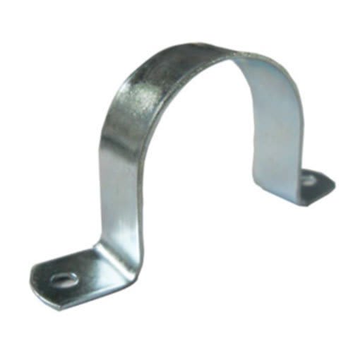
1. The connector is a clamp, something like the picture
u-clamp-500x500_iowfgy.jpg

It hold two parts under two type of loading... one is vibration profile, another one is acceleration in mini second - shock
I was wondering if HCF is a concern and then using Goodman diagram for the check?
Mean stress will be collected from vibration load profile and alternating stress will be from acceleration loading.
Does it make sense to you?

2. In other case, ground-air-ground, we check for LCF by taking the max stress and finding the cycles from the S-N curve... the number of cycles usually more than 10, 000 cycles... based on the textbook, I am confused here why we call it LCF analysis yet the cycles is more than 10,000 cycles? Is it if the stress is below yield, it is fine to S-N curve?

Thank you!
 
Hi rb1957, for the connector, it would the inertia will be applied for 6 times in three directions in the testing
 
Here is a nice quote from a white paper

How Fatigue Data are Obtained
Engineers and technicians obtain fatigue data much as they do tensile data. The test machines
are similar to that shown for tensile tests and similar specimens are used. The chief difference
lies in the application of load. In an HCF specimen test, the load is applied to the specimen at 30
to 60 cycles per second and often at much higher frequencies.
In engine components where HCF is a concern, turbomachinery designers observe what is
referred to as a material's fatigue strength. This is determined by running multiple specimen
tests at a number of different stresses. The objective is to identify the highest stress that will
produce a fatigue life beyond ten million cycles. This stress is also known as the material's
endurance limit. Gas turbines are designed so that the stresses in engine components do not
exceed this value including an additional safety factor.
LCF testing is conducted in a similar fashion, the chief difference being the need for higher
(plastic) loading and lower frequencies. As shown earlier, the graphic results appear similar but
the lives are much lower and there is no "fatigue strength" per se. Still, components subjected to
LCF loading are designed such that stresses remain well below the average lives determined in
the LCF tests.
The fatigue life graphs are informative in a number of ways. In addition to determining the
maximum stress allowed for a component life to meet ten million cycles, they can also be used
to compare the durability of different alloys and show temperature and other environmental
effects.
Tensile (stress vs. strain) curves and fatigue (stress vs. life) curves also show us why fatigue is
such a concern. If we look at the tensile behavior shown in Figure 4, we can see that the
breaking strength is over 140,000 psi. This means that 140,000 lbs. can be hung from a bar with
a one square inch cross section indefinitely. If we look at the HCF plot in Figure 5, we can see
that the fatigue strength for Alloy B is less than 40,000 psi. This tells us that for infinite life a
material's ability to resist a cyclic (vibratory) load is much lower than its ability to resist
 
LCF is IMO high load or possibly high Kt meaning that it is elasto-plastic fatigue, which is quite different to typical (elastic) fatigue, probably requires strain based fatigue analysis. I'd say LCF lives would be < 1000, maybe < 10000, cycles.

HCF could be either of ...
1) very high frequency fatigue where dynamic effects come into play, or
2) very long service lives (so an enormous number of cycles build up at a "normal" frequency over a very long time.

I am surprised that this U-clip is attracting such attention. If vibration loading, would an isolator help ?

another day in paradise, or is paradise one day closer ?
 
Yeah... I could understand when is the HCF coming...

For LCF that I had been doing, we just pick the max stress from the LCF loading... and use S-N curve for fatigue analysis... and the required life cycles is min 10,000 cycles or even more per customer requirement...Does it mean LCF here not referring to the number of cycles but the type of loading?

It is called LCF, ground-air-ground, because it takes a long period to complete a cycle?

 
I think you're misusing the term "LCF". It is poorly defined but to me LCF invokes an element of elastic/plastic behaviour in the far-field stress. The near-field stress, in the Kt zone, will most often be plastic but we don't take that into account (beyond how we normally do fatigue, based on far-field stress). The usual paper-clip example of fatigue is an example of low cycle fatigue. The elastic/plastic behaviour requires different analysis, ie not your normal s/n curve.

HCF is also poorly defined, but to me it is driven by the frequency of the load input. < 0.01Hz is probably clearly "normal" fatigue, > 100Hz is probably clearly HCF, and between is somewhere in the middle !!?? The very high frequency of the load input is the key thing, introducing some dynamic effects into the "normal" fatigue analysis.

GAG cycle is typical of "normal" fatigue (using a typical s/n curve), because it is not elastic/plastic and it is not driven by a >100 Hz load input.

another day in paradise, or is paradise one day closer ?
 
Hi rb1957, I agree with you as the further I check back, it might be defined that way ---> LCF for GAG...

However, for some LCF, it is using Miner's rule. I believe that should be the right way.
 
Status
Not open for further replies.

Part and Inventory Search

Sponsor