Continue to Site

Eng-Tips is the largest engineering community on the Internet

Intelligent Work Forums for Engineering Professionals

  • Congratulations KootK on being selected by the Eng-Tips community for having the most helpful posts in the forums last week. Way to Go!

Sign Convention of shear on a Vertical Beam.

Status
Not open for further replies.

bluestar9k

Structural
Nov 11, 2016
31
With respect to a truss there are vertical members, horizontal members and diagonal members.
I understand the “shear displacement” for the diagonal and horizontal members; but, can not resolve the shear displacement for a vertical member. Specifically, which end is considered the “left side” for positive shear.

Consider a vertical beam connected to Node A at the top and Node B at the bottom. If positive shear is applied to Node A with respect to Node B how does Node A displace with respect to Node B? To the right or to the left?
 
Replies continue below

Recommended for you

Positive shear could be either way, but if you are defining the member as starting at A and ending at B, positive shear near A would be from left to right by the usual convention. Alternatively, if you define the member from B to A, positive shear near Node B would be right to left.

bluestar said:
Consider a vertical beam connected to Node A at the top and Node B at the bottom. If positive shear is applied to Node A with respect to Node B how does Node A displace with respect to Node B? To the right or to the left?

Positive shear applied at Node A does not indicate anything about displacement of A with respect to B. For example, a simple span beam may have positive shear at A and negative shear at B but neither support is displaced.

BA
 
I use the international convention for actions on members. Using a right hand coordinate system, the + or - direction of the force on a positive face has the sign of the force sign. If the face is a negative face, then the sign of the force sign is the opposite. Eg., a negative direction force acting on a negative face is positive.

Dik
 
OK good, understood! If positive shear is applied at Node A the shear force would be from left to right. Yep, I knew the direction would reverse at Node B for positive shear. THANKS!

Hey dik, might you have a link to the International convention? That might be worth a look-see.
 
I don't, but, I'll try to look it up...

Dik
 
Can the following Generalization be made about shear force sign convention?

A shear force, when applied at one end of a beam, is considered positive if it would create an imaginary clockwise moment at the opposite end of the beam.
 
Yup... but, the international convention also accommodates flexure and torsion.

Dik
 
Dik's international convention?

Z axis pointing up. X axis pointing right. Y axis pointing away.

Then, for simple span beam on X axis, gravity load is negative. Reactions are positive. Bending moment is positive. Torsion is negative for gravity load.

BA
 
Interesting that positive Y axis goes into the page instead of Z axis.

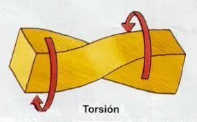
If you have a simple beam I don't understand how torsion is created in the beam from gravity. Can you explain this in a little more detail?
 
If you want the Z axis to go into the page, then the X axis must go from right to left. The right hand rule requires that X rotates into Y in the positive Z direction. Y rotates into Z in the positive X direction and Z rotates into X in the positive Y direction.

Torsion results from gravity load acting at an eccentricity. If the eccentricity is positive, (positive Y), torsion is negative since the load is negative. If the eccentricity is negative (negative Y) the torsion is positive.

That is the way I believe it should be but dik may wish to comment.

BA
 
With regard to torsion, the applied torsion in the span is negative which means that the torsional reactions are positive, so torsion varies from positive at the left to negative at the right, similar to shear variation.

BA
 
It seems that part of the problem/confusion is that the beam in this case is in a vert. orientation, so there is some problem visualizing things. Why not draw the beam in the vert. position on a piece of paper, with all its loadings. Then, rotate the paper 90̊ clockwise and apply your normal process and thinking for drawing shear, moment diagrams, etc. Otherwise, I agree with Dik and BA.
 
dhengr,

If Node A is at the top and B at the bottom, it would be better to rotate counterclockwise so that A is on the left and B on the right.

BA
 
With respect to gravity induced torsion on a simple horizontal beam.
Torsion_zaus2m.jpg


1. How does the force of gravity become eccentric to induce torsion?

2. Additionally, how significant is gravitational torsion with respect to a beams total load capacity?
 
BART: Not mine... it's predicated on the direction of the force on the direction of the face... been around for nearly 50 years that I'm aware of.

Dik
 
bluestar said:
1. How does the force of gravity become eccentric to induce torsion?
A gravity load such as a wall can be positioned eccentric to the beam's shear center.

bluestar said:
2. Additionally, how significant is gravitational torsion with respect to a beams total load capacity?
Can be very significant. A steel WF or I beam is weak in torsion and may fail at a load much lower than it could carry if the load was concentric. A square or round hollow section is strong in torsion, so its capacity may not be significantly affected if the eccentricity is minor.

BA
 
BART... have to be a bit careful. A local coordinate system as well as a global coordinate system can be used. Maybe should have mentioned that the International Coord sys starts with a right hand coordinate sys...

Dik
 
Yes dik, loads are usually input in a local coordinate system. If a member is defined as Node A to Node B, the local member X axis starts at A and is directed toward B. The other two axes start at A and are directed in accordance with the orientation of the member and the right hand rule. To solve for forces in a frame, local coordinates are transformed to global coordinates using a transformation matrix. When calculations are complete, global coordinates are transformed back using the inverse transformation matrix. Both local and global coordinates are consistent with a right handed system, although that is just a matter of convention. A left handed system would work equally well.

It has been a while since I wrote a frame program, so I'm sure to be missing a few details, but that is roughly the way I remember it.

BA
 
Status
Not open for further replies.

Part and Inventory Search

Sponsor