Continue to Site

Eng-Tips is the largest engineering community on the Internet

Intelligent Work Forums for Engineering Professionals

  • Congratulations KootK on being selected by the Eng-Tips community for having the most helpful posts in the forums last week. Way to Go!

Significant numbers, interperting size limits 7

Status
Not open for further replies.

Fronush

Mechanical
May 8, 2019
20
New here, Long time Engineer currently retired. But often asked to provide answers. The typical topic often asked is the definition of significant numbers in interpreting dimensions on drawings.
If an item dimension is 3 decimal paces on the drawing with a unilateral 3 decimal tolerance I suggest measuring to 3 decimal places is all that is required. That the significant numbers defines the accuracy of measurement needed. A part put out for quote with 3 decimal dimensions can be done by a shop with nothing more than micrometers without vernier 4 decimal capability but often told I'm wrong. If so then what is the purpose of significant numbering?
 
Replies continue below

Recommended for you

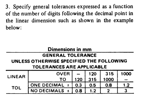
Significant numbering can mean anything, providing it was explicitly specified on a drawing:
Capture_ujav0w.png

It doesn't have to look exactly like this, but it has to explain, how to interpret number of significant digits.

"For every expert there is an equal and opposite expert"
Arthur C. Clarke Profiles of the future
 
Fronush,

Your measurement equipment should be sufficiently more accurate than the tolerances it is being utilized to measure. "Sufficiently" is to be determined by your quality team depending on how small (or large) your tolerance is, process limits, and process as well as measurement capability. This is quite a complex topic, suffice to say that three decimal place tolerance =/= three decimal place measurement (at least not in many cases).

Lets take a simple case though. If the tolerance is +0.001/-0.000 and unless there is 100% inspection and measurement error is 0% (the former, maybe - the latter, definitely not) the process/control limits are going to have to be within those bounds, say +0.0007/+0.0002 for arguments sake. One is going to need something which measures to a fourth decimal place to be sure that the measured value is within the control limits as well as to calculate useful statistical data about the process.
 
ASTM E-29-13 (Standard Practice for
Using Significant Digits in Test Data to Determine
Conformance with Specifications) describes two methods of rounding data.
 
The rule of thumb I've always used is that the measurement system must be able to resolve 1/10 of the tolerance. So if the tolerance is +0.010/-0.000 then you only have to resolve 0.001. But if the tolerance is +0.001/-0.000 then you have to resolve 0.0001. More importantly, you need good gauge R&R. That involves repeatedly measuring the same group of parts (which ideally span the entire tolerance range) by multiple operators. If this yields the ability to resolve within 10% of the tolerance range then you've got a measurement system you can count on.

----------------------------------------

The Help for this program was created in Windows Help format, which depends on a feature that isn't included in this version of Windows.
 
That's assuming the drawing is for quite a few parts. If on 10 items I wanted .003" clearance between a pin and hole and use +/- .005 as tolerance then at maximum material condition I would have to dimension a size difference between the pin and hole so at MMC there is .003" if the parts came and the pin .5051" and the hole was .5079 at MMC there will be no assembly problems. I always considered a dimension last decimal place number as the measurement tools accuracy. Lets assume it a micrometer. With significant numbers a measurement is accurate to the decimal place preceding the last and the last is an estimate. But in dimension the last is the accurate decimal and in measuring the device must be accurate to the last decimal of the dimension given and any additional decimals measured are estimates. Therefore a line on the barrel of a micrometer is in thousandths and any additional decimal is an estimate of the distance to the next line. Applying the rule of rounding an estimate of .0004 would be .000. My example will then be pin .505" and hole .508"
 
Fronush,

Fronush 14 May 19 16:41 said:
That's assuming the drawing is for quite a few parts.
Certainly concerns like process capability are much more prevalent as the quantity of parts to be produced increases. Though cost plays into this as well - if you're making 100 parts that take 30 seconds to make and cost $1 each then maybe you're not so concerned about process limits/capability and the like. If a few (or more than a few) get scrapped no big deal. But if you're making 100 parts that take 6 hours each to make and each cost $1000, you would want to make darn sure your process is capable to reduce scrapped parts.

Fronush 14 May 19 16:41 said:
I always considered a dimension last decimal place number as the measurement tools accuracy.
The drawing and associated dimensions/tolerances in no way dictates the measurement tool or method to be used, unless explicitly stated - which I would typically not recommend.
 
Then would that be a conflict with significant numbering? Significant numbering is used quite a bit in other Engineering. If an error is made and that is what tolerance is because nothing can be made perfect! If in fact like my previous example it did not make a difference requiring measurement beyond thousands will add to cost. On the other hand if it were required to be more accurate then additional decimals used.
 
Fronush 14 May 19 17:23 said:
Then would that be a conflict with significant numbering? [...] If in fact like my previous example it did not make a difference requiring measurement beyond thousands will add to cost.

The only thing required by the print is that the part meet the dimensions and tolerances stated. If significant digits/decimal places are tied to a table of values showing standard print tolerances as CH noted then that in no way changes what I said - the significant digits/decimal places in that case would just dictate what tolerance range is utilized. This still does not directly dictate the measurement tool/method/accuracy.

Fronush 14 May 19 17:23 said:
On the other hand if it were required to be more accurate then additional decimals used.

Both myself and dgallup showed an example where a tolerance of 3 decimal places (+0.001/-0.000) would almost certainly require measurement accuracy of at least 4 places.
 
Don't misunderstand my questing, I'm acting as devils advocate. If I were to tell a machine shop their part was rejected and provide the example give with the 1/10 of tolerance range I envision their reply being where is that proven. Significant figures are well defined in many Googled sites. The reasoning is simple to follow. In the example +.001/-.000 and 4 places are used with 10% is +.0011 or -.0001 acceptable? Where can I find examples of this 1/10 requirement? Furthermore to argue the opposite side is +.00101 or -.00001 acceptable or not?
 
Fronush 14 May 19 20:35 said:
In the example +.001/-.000 and 4 places are used with 10% is +.0011 or -.0001 acceptable?

Per the print, no. You can go out to the millionth decimal place my answer would not change.

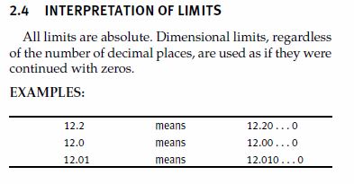
If you go by ASME in Y14.5-2009 section 2.4 it has the below verbiage which says as much. In the 2018 edition this is section 5.4 and is almost identical.

limits_nzrvzi.jpg


Now if engineering is required to assess whether parts that are borderline or very barely out of tolerance are useable because of (A) high reject rate in which reasonable measures have already been taken to improve the process (in which case I would be expected to consider a loosening of the print tolerance) or (B) a batch of bad parts which are being asked to use due to quantity/cost/already installed/etc.., that is a different question.
 
Exactly, the first thing we were told in our undergrad metrology lectures was decimal places alone do not imply accuracy. In fact they are quite often used as smoke and mirrors. 12 is no less "accurate" than 12.000000001

 
I have seen that designation 12.2 means 12.000..00 and so on in some other thread but later in the thread it mentioned it was for metric which I can understand because metric mm is 1/25.4 of an inch. Also above 10% was mentioned so that contradicts 000....000. I'm also thinking that 10% would be more appropriate for metric simply because .1mm is 10% of a mm. In addition most machinist handbooks explain rounding and proper use plus if the number preceding is even 5 is rounded down, odd is rounded up. To add to the problem measuring tools are only accurate to a limit. For example a Starrett Digital micrometer capable of displaying .00005 is only accurate to .0001. In addition a size difference of .001 makes little difference to a large dimension such as 12 and it does to a smaller number like .12
Lectures are one thing, but hard facts are needed to convince someone that has been doing something for years another way. In addition nothing provides reasoning why significant numbering does not apply.
 
Fronush,

Metric/inch does not matter - the requirement is the same. If I understand correctly (which I believe I do) the 10% was in reference to a rule of thumb regarding expected measurement accuracy/resolution in reference to the print tolerance, not the other way around or anything else.

I realize the implications of reality - I'm not talking about theory or lectures. As an engineer/designer one must take a stand somewhere, this is important. In regards to tolerances, when I put a tolerance on a print I need it so be considered absolute - if I put a limit on a dimension they must be considered rigid, limits out to the infinite decimal places. I am supported on this by standards such as the one I quoted in Y14.5, I'm sure ISO has a similar requirement. If someone brings a part to me which is 0.0001 outside the tolerance, my initial response will be that it is unacceptable - if this brings pushback from management or quality for reasons of cost, lead time, practicality, etc.. then a conversation can happen like I said about either providing a temporary permit for a batch of parts or a widening of the print tolerance. These are the practical implications of working in the real world.

But if I don't take an initial stand then the tolerance becomes meaningless. If 0.0001 is okay, what about 0.0002? Or 0.0003? Where is the cutoff now that the tolerance is not considered absolute?
 
I'm the same, I calculate the limits, I do not pick a number out of a hat. But typical drawing and a dimensional tolerance chart like .XXX = +/-.005 When calculated tolerance is lets assume +/-.006 I use the listed number. The added cost limiting the tolerance .001 will not increase the cost. Keeps the drawing simple otherwise every dimension will require tolerance rather than those that require it "as noted" If I need to limit the tolerance to 4 places I'll use the .XXXX listing if possible if not then "as noted". Make the drawing simple and a rocket scientist is not require to make measurements. No one is asking to change tolerance, significant figures are well defined and will only change a fraction of the limit. Granted when making a high quantity upper limits are not to be done, minor shift in something will begin to make a lot of junk!
I know too well manufacturing wants to make tolerances as big as possible. Too often when changes are requested and denied they do it anyway. Keeps the guy buying the scrap happy! But on the other side a guy using a new Starrett Digital micrometer display in .00005 don't realize it's only accurate to .0001. So knowing that I design knowing limitations. Yet how many are attempting to measure with digital calipers? You telling me that dimensions that are in 3 place decimal will not be usable if the measured amount exceed the 3 decimal tolerance by .0003"? Rounding will limit it to .0005 depending upon the preceding is odd or even. If it is that critical then wouldn't using 4 place decimal or "as noted" limit?
I eventually left Engineering primarily because the majority of my time was spent trying to make an existing product cheaper! Now I'm often requested to help instruct others on how to do it for best results.
 
In metric dimensioning the number of decimal places does not indicate tolerance. There are plenty of widely available measurement devices that are far more accurate than a micrometer. We manufacture parts in the millions that have tolerances of 1 micron, we have no problem measuring or meeting the tolerance. Horses for courses.

----------------------------------------

The Help for this program was created in Windows Help format, which depends on a feature that isn't included in this version of Windows.
 
Yes I understand that, the meter is "fractioned" into dm,cm,mm,um and nm but inch isn't. Decimals are a means of division by 10. Nor am I speaking of Automotive high production large facility operations. The small machine shop keeps the small companies operational. A shaft for a conveyor belt does not need um detail. Typical pillow block bearing is usually .003" over shaft size and use cam or set screw to attach to the shaft. In my area there are quite a few large companies that are supported by small machine shops. None of which have a CMM or means of accurately measuring beyond .0001 and a few that are limited to .001" yet they successfully support their customers. I can assume that areas in automotive require high degree of accuracy but I know many holes in the body do not! Most often the hole exceeds the bolt diameter by quite a bit or is a slot.
 
Fronush,

The concept of significant figures only applies to values that are measured or derived from measurements. Following significant figure rules in the calculation and reporting of values is a way to maintain and convey a rough idea of the uncertainty involved. The practice is far from universal though. More sophisticated and accurate methods are used in many cases, while uncertainty is essentially ignored in others.

Size limits and other dimensional tolerance values are exact specifications, so the concept of significant figures does not apply to them. It's not entirely clear to me what connection you're suggesting exists, but it sounds like you're actually referring to the decision of whether to accept or reject parts. That's a somewhat separate issue, and can be substantially more complicated than determining the meaning of a drawing requirement.

You mentioned that you are often asked about this topic. Do you have any examples of specific questions?


pylfrm
 
Yes I'm talking about measured dimension. Not that a number on a drawing can be interpreted differently. Simple example Print dimension of a shaft is 6.000" +/-.005 When completed shaft is measured by customer it is 6.0051", is this acceptable? Or is it rejected? Pushing that farther it's measured 6.00501, acceptable or not? The question is simple and accepting the rules of rounding for 5 is any digit up to 4 beyond the last decimal on the tolerance to be considered. Dimensional measured as in the example of a print as above of the produced item as 6.0054 or 5.9996 to be considered as in tolerance as per Significant figures and rules of rounding. Print dimension is 3 place decimal as well as tolerance.
 
The part should be rejected if it is even one angstrom outside of the tolerance. If the part can consistently hit 0.0000000000000001 mm outside the zone, the process can be changed to put it 0.0000000000000001 mm inside the zone.

I can't entirely express my frustration at repeated manufacturing requests to bump a tolerance that is consistently out by some small amount, only to have the new parts exceed the new, larger zone because they figured instead of being out a little on a high quality machine they could now move the part to a piece of sh*t machine because of the larger zone.

The ASME rules are simple - the limits are the limits. Don't promise parts that cannot be reliably made.
 
Status
Not open for further replies.

Part and Inventory Search

Sponsor