Continue to Site

Eng-Tips is the largest engineering community on the Internet

Intelligent Work Forums for Engineering Professionals

  • Congratulations KootK on being selected by the Eng-Tips community for having the most helpful posts in the forums last week. Way to Go!

Significant numbers, interperting size limits 7

Status
Not open for further replies.

Fronush

Mechanical
May 8, 2019
20
New here, Long time Engineer currently retired. But often asked to provide answers. The typical topic often asked is the definition of significant numbers in interpreting dimensions on drawings.
If an item dimension is 3 decimal paces on the drawing with a unilateral 3 decimal tolerance I suggest measuring to 3 decimal places is all that is required. That the significant numbers defines the accuracy of measurement needed. A part put out for quote with 3 decimal dimensions can be done by a shop with nothing more than micrometers without vernier 4 decimal capability but often told I'm wrong. If so then what is the purpose of significant numbering?
 
Replies continue below

Recommended for you

1/10 is a ratio of tolerance to needed measurement accuracy. The units do not matter.
 
shows difference between metric and inch tolerance dimensions. Some place I when searching was only listed as chapter 5 and all prefixes on chapters started with 5 but the above show the same and implies decimal significance.
10% of anything is still 10% of the same item length, weight or anything else! BUT 10% on 1mm and 10% of inch is not an equal number! A conversion standard have been developed and agreed upon and that is 25.4mm = 1 inch! The same as 10% of C is not equal to 10% of F. The apples and oranges example! 10% of an apple is not the same as 10% of an orange!
Have completed EE and ME and headed toward Chemical engineering until marriage and children took me out of University and in the Job market. I'm sure you all have seen it many times and the same in all engineering 101 except the item changed! It goes something like John and Joe needed a cube of steel for a school project, John gave a drawing to a local machine shop 2.000" X 2.000" X 2.000", Joe's drawing was 2.00000" X 2.00000" X 2.00000". When John picked up his block the bill came to $25.00 but Joe was shocked when presented with a bill of $2,500.00.
I'm retired for 10 years, I'm not going to invest in documents I will never use! Having a father that was tool and die, during WW2 he was returned to GM after enlisting in the Army because the plant in Linden NJ was converted to fighter planes! I can tell you how many times he had to correct engineering. One of the things he worked on was the machine gun in the fighter plane, If it failed the pilot became nothing more than a target! I know and operate all the machine shop machinery as I mentioned and love AutoCad type drawing. But even AutoCad type drawing aids will use significant numbers and will round as per rounding rules. I am very familiar with precision and require compliance to limits I set. But I'm also aware of what is necessary and what is not! I provided a question but get nothing more than metric rules! Who is the smart one? The Engineer or the guy in the shop trying to make the part? Engineering to me is simply to supply a "road map" to the fabricator making the part in easy to understand format not requiring lengthy interpretation and the measuring tools he has, most machine shops require the machinist to have a standard set of measuring tools. Sure the 25% reduction in tolerance for inspection in high production to catch a trend toward out of specification but try to explain why a part that was rejected being 1 of and is .004" of a .005" limit!
 
What is in that PDF is a dimensioning convention to tell the difference between Decimal Inch and Metric tolerances. It doesn't have anything to do with significant digits - it's to tell if someone made a mistake when they created the drawing or reference material by seeing if they could follow a simple rule. It's like giving an F on a college paper for misspelled words; if the writer is so careless with the simple things, then they are probably just as careless elsewhere. Saves time - just throw it back.

Oh, and that rounding on drawings? Yup. I've seen models like that go out where the rounding ate half the available tolerance when the shop imported the model into their CAM software.

About the story. Sure. They gave someone dimensions without tolerances, no one asked what was required, and they went off and wasted a pile of money. I do love a good joke. Since no angular dimensions were provided I bet the sides were out of square by 30 degrees, right?
 
1/10 is not a metric rule. You said it yourself, 10% of anything is always 10%. If your tolerance is .001 inches your measurement accuracy should be around .0001. If your tolerance is .025 mm, your measurement accuracy should be around .0025mm.

Anything that is out of tolerance has grounds to be rejected. It is at the engineers discretion if they want to accept the deviation, and that decision could be based on a number of things. But it is spelled out in the ASME standard. Per ASME the tolerance is absolute and interpreted to be followed with zeroes.

This thread has the relevant part of the standard copied in there Link

By your logic if you had a shaft and hole/bore that both had three decimal places tolerances. Both could be .00044" out. You could have almost .001" less clearance than the designed minimum clearance, and with your rounding rules, everything would be in spec. I could definitely see a design where this would not be acceptable. If the print is designed per the ASME standard then the parts are out of spec. If you design to a different standard which incorporates the rounding rules you specified, then you would be correct, as long as it's clearly spelled out what standard is used, and the prints are made accordingly.
 
Hmmmm maybe I'm reading wrong or in the wrong forum. "If the print is designed per the ASME standard then the parts are out of spec. If you design to a different standard which incorporates the rounding rules you specified, then you would be correct, as long as it's clearly spelled out what standard is used, and the prints are made accordingly." OK I agree!!!
What if no standard is listed and drawing made with coordinate/linear format? I can understand GD&T being absolute or true position so no deviation is acceptable. I keep referencing coordinate but possibly getting a GD&T reply. I'm speaking in oranges but in a apples forum. Reference has been made that linked this site and I foolishly followed it!
The question is if a drawing is in coordinate format, no specified standard is listed what general rules apply? Would it be safe to assume significant numbering and rounding? In this case I'm not the Engineer nor the Fabricator but sticking my nose in a another forum discussion as to how dimensions are interpreted. My attempt is to provide helpful information.
 
A print that does not have GD&T can still be to ASME Y14.5M standard. A lot of prints I've seen have a default "DRAFTING PER ASME Y14.5M UNLESS OTHERWISE SPECIFIED" even if just linear dimensioning is used. The standard defines rules that are applicable to when just linear dimensions are used. In general I would interpret a print to ASME Y14.5M unless it is otherwise specified, as that is what is most commonly used in my experience.

If no standard is referenced anywhere, then you may have found a gray area, which is exactly why these standards were developed. If it were me, I would just defer to ASME Y14.5M unless it was explicitly stated otherwise. And if it came down to a legal argument, where no standard is explicitly specified, I think a case based on a professional and well established standard would do better.
 
Seem this issue as caused quite a bit of confusion. I found in another topic in the forum while looking for more information.

"I talked with Paul Drake (author of Dim & Tol Handbook (McGraw Hill)).

His suggestion is to use the same general tolerancing method as we always have and ignore the trailing zero rule.

He is going to attempt to get this clarified in the next ANSI Dim & Tol edition. (Due out soon). Hopefully this rule will either be omitted or they will have a method of general tolerancing other than limiting every dim on the dwg."


Also
"You have to specify it on each dimension that requires a non-generic tolerance. Also note that the no trailing zero requirement is only on metric dimensioned parts. You can still have a title block tolerance block for those dimensions that are designed to a precision that they have a non-zero value."
 
You're talking about this thread?

It seems to me that they are discussing formatting issues, and not disputing paragraph 2.4 in ASME y14.5M-1994 (which is even posted in the thread).
 
If a standard is not being followed then you will have more problems than just significant figures/rounding which you are concerned about. Traditional dimensioning is inherently ambiguous for things other than what Y14.5 defines as a Feature of Size (and even then is subject to some ambiguity/nuance in certain cases but less so) and often requires integration of special notes and in some cases description of how a feature should be measured to achieve some semblance of expected conformance.

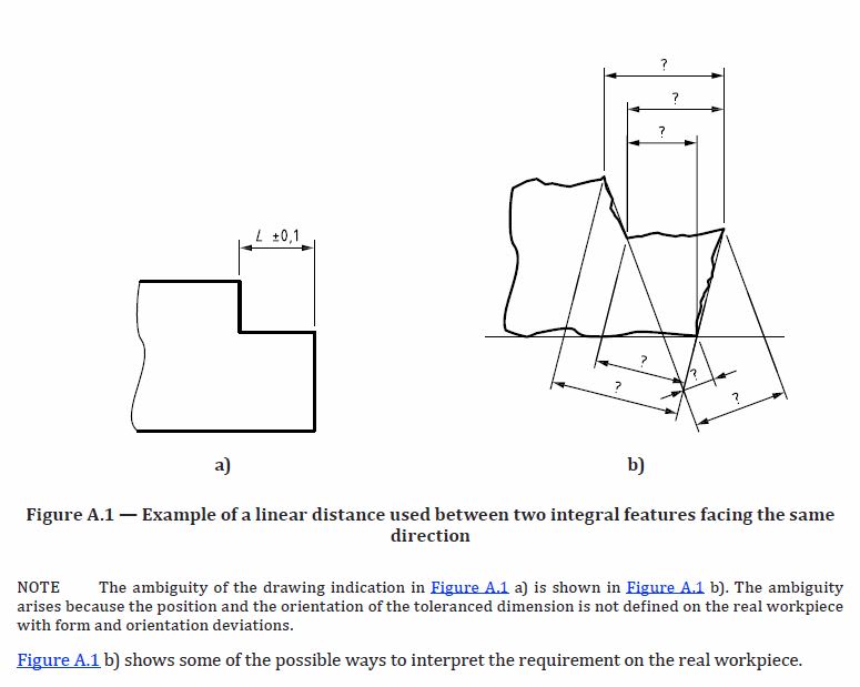
Below is an example of what seems like a simple linear dimension between two surfaces which is in reality extremely ambiguous. Utilizing the universal "language" of ASME GDnT or ISO GPS minimizes such ambiguity. If no standard is specified, two different suppliers or even two different operators could give wildly different measurements - significant figures would be the least of your concerns.

ISO_GPS_14405-2.2018_Fig_A1_mcf5ro.jpg
 
I do understand that GD&T defines surface outline better than Coordinate. Yet something like this is in Wikipedia "According to the ASME Y14.5-2009[2] standard, the purpose of geometric dimensioning and tolerancing (GD&T) is to describe the engineering intent of parts and assemblies. The datum reference frame can describe how the part fits or functions. GD&T can more accurately define the dimensional requirements for a part, allowing over 50% more tolerance zone than coordinate (or linear) dimensioning in some cases. Proper application of GD&T will ensure that the part defined on the drawing has the desired form, fit (within limits) and function with the largest possible tolerances. GD&T can add quality and reduce cost at the same time through producibility."
Most of general drawings which are drawn by need and not engineered are quite prevalent. When something has broken down sending the broken part to a machine shop is not really a good idea but I get it quite often still having a small machine shop to help a local poultry plant that I was the engineer prior to my retirement. The replacement they hired was a waste of time! Eventually they decided they didn't need and staff engineer. Quite often I/m requested to make a better part because of repeated failures. The plant is completely automated, very little is done by human hands. Those equipment manufactures will not supply drawings just replacement parts, but when I check replacement parts I find that dimensions are not as they should be! Most of the machinery is manufactured in Germany and Denmark use metric dimensions! So it seems these companies do not have good quality control which is odd for those countries listed. Possibly cost demands require manufacturing cost that usually results in larger tolerance Yet those part I build or send drawings to other shops work well and I hold the dimensions to the last decimal and nothing beyond! Failure rate drops dramatically. Plus replacement cost is lower!!
 
Status
Not open for further replies.

Part and Inventory Search

Sponsor