Continue to Site

Eng-Tips is the largest engineering community on the Internet

Intelligent Work Forums for Engineering Professionals

  • Congratulations KootK on being selected by the Eng-Tips community for having the most helpful posts in the forums last week. Way to Go!

Silicone Joint Calculation

Status
Not open for further replies.

GoncaloPT

Structural
Jun 9, 2020
24
Hello!
Hopefully someone here can help me!


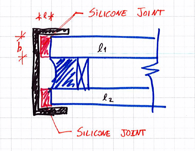
I am currently analyzing a glass DOUBLE IGU panel supported on both sides by structural silicone (please check pictures below).
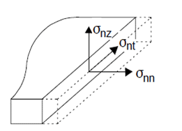
I would like to know if there is any way to calculate the maximum stress on the silicone as a function of the weight and height of gluing the panel.
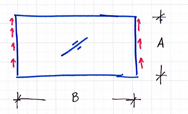
Currently, my spreadsheet is calculating the shear area of the silicone joint ( b x A) and divide it by half the height of the glass panel.

tau = (Weight/2)/(bxA) - Please note the pictures below

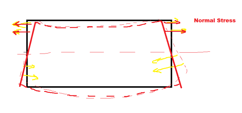
But I would like to know if there's any better way to design this silicone joints including any possible peel failure. I don't have much faith in this approach. I'm also afraid that some normal stress could arise due to bending in plane direction of the glass at mid span (although not significantly as the glass is pretty rigid). Does someone have any tips on how to properly design silicone joints?
image_ni8ww0.png
image_srlzid.png

image_t1tbbc.png
image_hcpykf.png
 
Replies continue below

Recommended for you

Generally, supporting dead loads of glass exclusively with structural silicone is avoided, due in part to issues with creep. Some sort of positive mechanical support would typically be considered, with the silicone only supporting the lateral. I believe that the allowable silicone stress for permanent loads is 1/20 the values for temporary loads.

In regards to the design of structural silicone overall, I would recommend the technical manuals from Dow (available online), as they are pretty well comprehensive. I believe that there is a version that addresses attaching IGU's to framing, and a second version that addresses the edges seals of the IGU itself.

While the overall intent isn't especially clear here (i.e. geometry, loads, interior/exterior), I would expect that you will have a hard time getting this concept to work (and/or getting the glass manufacturer to warranty). IGUS are generally supported on all four sides for a reason, as edge seal failures will lead to fogging of the IGU's. And typically glass manufacturers want the gravity support to be a certain distance away from a corner.


Thank you for your response @jjl317.
Yes, I agree that this isn't the ideal method for support, but my goal is specifically to develop a tool that sets a limit on this type of support. There's some silicone manufactures that have their products certified (according to ETAG 002) for long term resistances (the values are pretty low as expected).

Do you have any link for the technical manuals mentioned? If you could provide the link or pdf I would much appreciate it, as I couldn't find them on google.

As far as breaking the sealing, the glass would be supported in the edge, so, each layer of the IGU would be glued (see picture below).

image_qb43m7.png
 
Here is the manual I often refer to: Link

As jjl317 mentioned, this is not an ideal way to support an IGU. You would typically want some sort of dead load support, usually around 100-200mm away from the bottom corners. I get that you're trying to develop a tool to show the stress in these seals, I just wanted to add my 2 cents for anyone elses reference really.

Also, the diagram you have provided shows that one of the glass layers is a laminated pane (This might just be a diagram you found for reference...looks like SJ Mepla). If one of the layers is in fact laminated, I would strongly advise against allowing the silicone to come into contact with the PVB...as silicone usually degrades PVB.

Another question...how is this seal going to be installed? It looks like it would have to be a blind seal...which in my experience will not go well.

Any questions mate let me know.
 
Dear @NalaCap0ne,
Yes, this diagram is just for reference.
I'm sorry but could you please explain what is a blind seal? I'm not a native speaker and more technical vocabulary Is sometimes a bit harsh to understand (I tried to google it but it just appear seals with red eyes lol). Is it a joint that doesn't get ventilation to cure?

We usually glue some aluminum U-channels to the glass IGU (with silicone) and hang the panels on the aluminum profiles (and I know that this isn't a very safe or proper way to support this type of application (specially in the long term) but that's how our systems are designed so far. I'm just trying to have a way to define a limit for such supports.

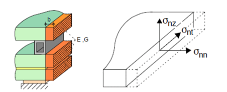
I'm trying to implement a way to properly verify the silicone shear stress and the shear peel fores between the adhesive and the adherent materials.

Thank you both for the manuals, I really appreciate it. It seems the approach they use for the shear is the same I was using.
 
Sorry about that mate. Its a bit wierd to explain, but I what I call a blind seal is any silicone seal where you cant directly control the dimensions of the seal. So for a typical curtain walling structural seal for example, you would put some sort of spacer, gasket, or glazing tape between the glass and the mullion which controls the depth of the seal. You woudl then fill the void created between the mullion and the glass with silicone, while the spacer, gasket, or glazing tape acts as a stop therefore allowing you to control the silicone bite. What results is a rectangular seal that you know the dimensions of for sure. I would class your seal as a blind seal however, because I imagine you probably apply a bunch of silicone inside the steel channel, then apply it to the glass edge. The issue with this sort of seal is it can often lead to inconsistent seals (i.e. a change in dimension throughotu the seal), and not knowing for sure what the seal dimensions are.

I hope this makes sense....
 
Ok I got it :) It's basically a way to make sure the silicone bite has the desired dimensions.
In that way, you are correct, there's really no way to make sure the seal has the desired dimensions.
 
Status
Not open for further replies.

Part and Inventory Search

Sponsor