nivoo_boss
Structural
Hello everyone!
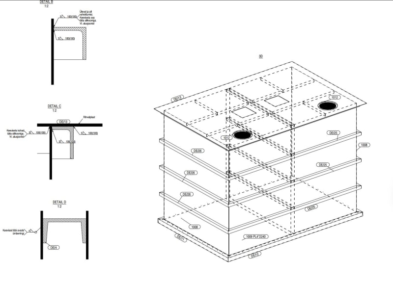
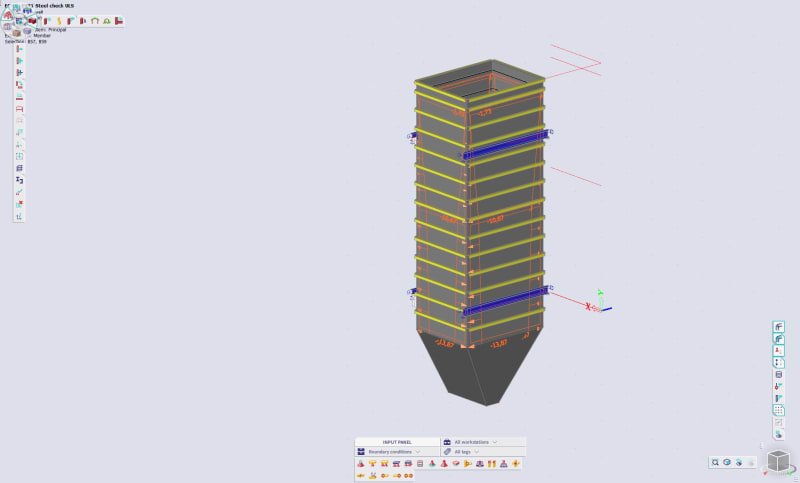
So I'm designing a steel grain silo with a capacity of around 33 m³ for the vertical part (class 1 according to EC 1991-4, under 100 t) - the cross-section is 2,0x2,6 m and the vertical section is 6,75 m high (so the grain would weigh around 300 kN at a unit weight of 9 kN/m³) . I've been studying the code for last 4 days and it has been quite overwhelming.
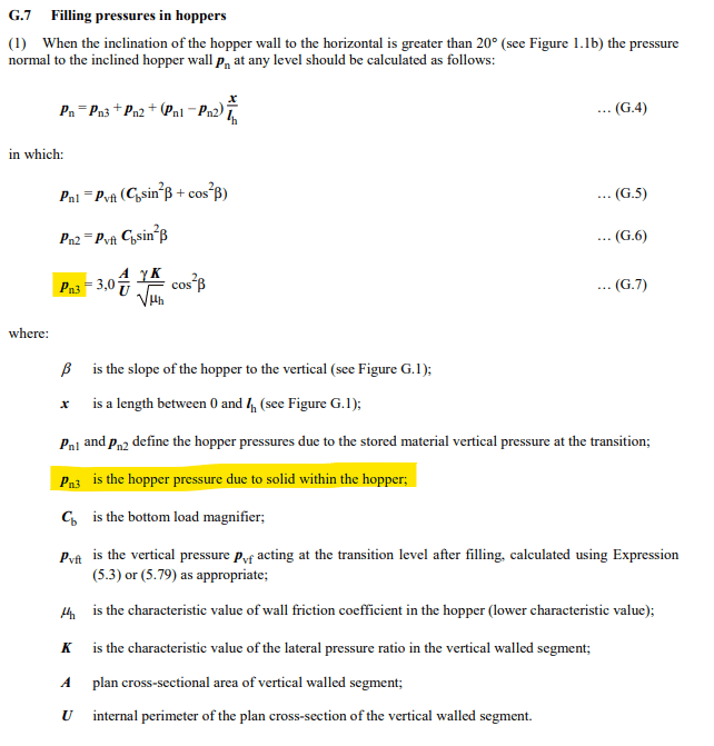
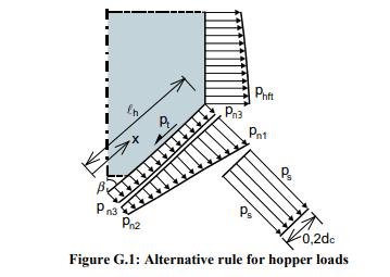
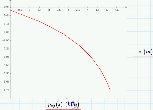
Is anybody here familiar with this particular Eurocode? I've calculated the frictional forces at eight different depths according to formula 5.2 in paragraph 5.2.1.1 in EC 1991-4 - now these results make sense - the net force seems to be quite realistic (around 165 kN I think). The frictional force pwf at equivalent surface level is 0,75 kPa and at the transition between the walls and hopper at a depth of 6,415 m it is 4,87 kPa. The formula from the code:
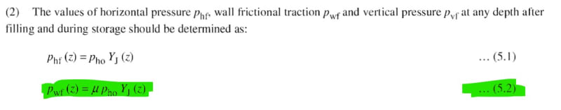
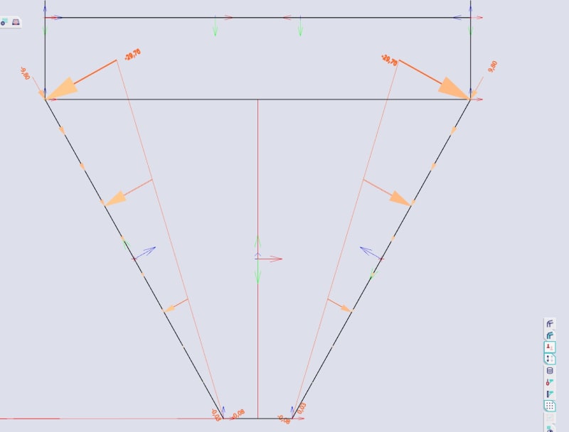
So is this the load I should add to my silo walls? I know it's not really linearly getting bigger but should I add it in my model in a way that it is a vertical surface load on my 2D element in model that has a value of 0,75 kPa at the top and 4,87 kPa at the bottom like a trapezoidal load?
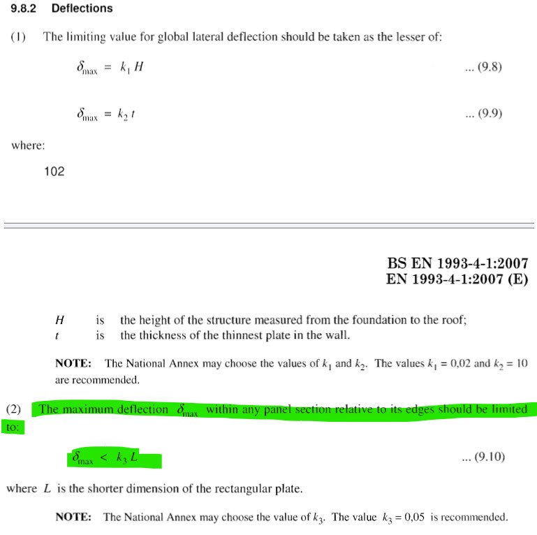
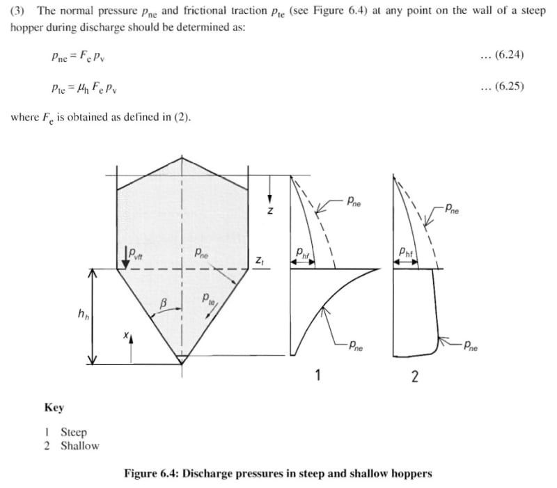
Anyway, my real problem is another formula (5.7) in EC 1991-4 on the next page:
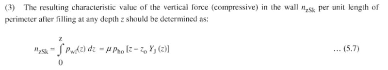
Now if I calculate these forces at the same depths as before for the frictional forces I get loads that are 0,13 kN/m at the equivalent surface level and 22,4 kN/m at the depth of 6,415 m. And the net force for this seems insanely high - like twice the force that the grain for this silo volume would actually weigh (around 665 kN?).
So what am I doing wrong? Any ideas?")
So I'm designing a steel grain silo with a capacity of around 33 m³ for the vertical part (class 1 according to EC 1991-4, under 100 t) - the cross-section is 2,0x2,6 m and the vertical section is 6,75 m high (so the grain would weigh around 300 kN at a unit weight of 9 kN/m³) . I've been studying the code for last 4 days and it has been quite overwhelming.
Is anybody here familiar with this particular Eurocode? I've calculated the frictional forces at eight different depths according to formula 5.2 in paragraph 5.2.1.1 in EC 1991-4 - now these results make sense - the net force seems to be quite realistic (around 165 kN I think). The frictional force pwf at equivalent surface level is 0,75 kPa and at the transition between the walls and hopper at a depth of 6,415 m it is 4,87 kPa. The formula from the code:
So is this the load I should add to my silo walls? I know it's not really linearly getting bigger but should I add it in my model in a way that it is a vertical surface load on my 2D element in model that has a value of 0,75 kPa at the top and 4,87 kPa at the bottom like a trapezoidal load?
Anyway, my real problem is another formula (5.7) in EC 1991-4 on the next page:
Now if I calculate these forces at the same depths as before for the frictional forces I get loads that are 0,13 kN/m at the equivalent surface level and 22,4 kN/m at the depth of 6,415 m. And the net force for this seems insanely high - like twice the force that the grain for this silo volume would actually weigh (around 665 kN?).
So what am I doing wrong? Any ideas?
![[thumbsup2]](/data/assets/smilies/thumbsup2.gif "[thumbsup2] [thumbsup2]")
![[wink]](/data/assets/smilies/wink.gif "[wink] [wink]")
![[thumbsup]](/data/assets/smilies/thumbsup.gif "[thumbsup] [thumbsup]")