Continue to Site

Eng-Tips is the largest engineering community on the Internet

Intelligent Work Forums for Engineering Professionals

  • Congratulations KootK on being selected by the Eng-Tips community for having the most helpful posts in the forums last week. Way to Go!

Silo design. Eurocode 1991-4 interpretation 2

nivoo_boss

Structural
Jul 15, 2021
130
Hello everyone!

So I'm designing a steel grain silo with a capacity of around 33 m³ for the vertical part (class 1 according to EC 1991-4, under 100 t) - the cross-section is 2,0x2,6 m and the vertical section is 6,75 m high (so the grain would weigh around 300 kN at a unit weight of 9 kN/m³) . I've been studying the code for last 4 days and it has been quite overwhelming.

Is anybody here familiar with this particular Eurocode? I've calculated the frictional forces at eight different depths according to formula 5.2 in paragraph 5.2.1.1 in EC 1991-4 - now these results make sense - the net force seems to be quite realistic (around 165 kN I think). The frictional force p[sub]wf[/sub] at equivalent surface level is 0,75 kPa and at the transition between the walls and hopper at a depth of 6,415 m it is 4,87 kPa. The formula from the code:
5.2_hqjgsd.jpg

So is this the load I should add to my silo walls? I know it's not really linearly getting bigger but should I add it in my model in a way that it is a vertical surface load on my 2D element in model that has a value of 0,75 kPa at the top and 4,87 kPa at the bottom like a trapezoidal load?

Anyway, my real problem is another formula (5.7) in EC 1991-4 on the next page:
5.7_fu8vg7.jpg

Now if I calculate these forces at the same depths as before for the frictional forces I get loads that are 0,13 kN/m at the equivalent surface level and 22,4 kN/m at the depth of 6,415 m. And the net force for this seems insanely high - like twice the force that the grain for this silo volume would actually weigh (around 665 kN?).

So what am I doing wrong? Any ideas? :)
 
Replies continue below

Recommended for you

Nivoo boss

Seems you are down the ‘rabbit hole’ which is Eurocode and the German love of
meaningless subscripts.

I can offer no advice, other than take it one line at a time and keep asking your self
“but what does it mean…”. Repeat. Repeat.

I once spent three months on EN 1312- part 3. And when I had finished, was given
eleven pages of Excel - listing known errors, typos etc (and that was on third or
fourth version of EN 312-3!).

There is nothing, absolutely nothing, that can not be made worse by the involvement
of the EU and it’s bureaucracy.

Currently on DVS 2205 – 2…

Good luck! You will need it.

Regards

Ed


Ed Clymer
Resinfab & Associates
England
 
I'm reasonably familiar with the code and have designed many silos and bins based of the loading in EC 1991-4.

EdClymer said:
Seems you are down the ‘rabbit hole’ which is Eurocode and the German love of
meaningless subscripts.

....

There is nothing, absolutely nothing, that can not be made worse by the involvement
of the EU and it’s bureaucracy.
Be careful there Ed. Your anti Europe bias seems to be showing its union jack colours. The irony here is that the EU code is actually formally the British code. The EU recognised that the British code was the most thorough and accurate code and adopted that.


nivoo_boss said:
So is this the load I should add to my silo walls? I know it's not really linearly getting bigger but should I add it in my model in a way that it is a vertical surface load on my 2D element in model that has a value of 0,75 kPa at the top and 4,87 kPa at the bottom like a trapezoidal load?
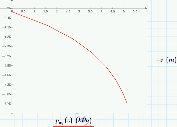
Applying it trapezoidal would be unconservative given the shape of the curve. If I am going to use vertical wall loads (often I won't bother) then I'll normally just apply the total amount uniformly as in most bin designs this would be conservative.

Here is my calculated curve:
temp_nu0k8h.png


nivoo_boss said:
Now if I calculate these forces at the same depths as before for the frictional forces I get loads that are 0,13 kN/m at the equivalent surface level and 22,4 kN/m at the depth of 6,415 m. And the net force for this seems insanely high - like twice the force that the grain for this silo volume would actually weigh (around 665 kN?).
Seems about right.... You have 9.2m wall circumferance which gives 22.4kN/m*9.2m= 206kN TOTAL WALL LOAD which is what I'd expect and also aligns with the calculated value of the pvf * A.

So your calculations seem to be correct by you seem to be having difficulty applying the loads.


All that said. Given this seems to be a rectangular bin, you barely need to worry about vertical loads for the bin design. It is the horizontal (perpendicular) wall pressures that will determine your design.
 
Thanks for great answer! But in your experience would`it be correct to assume hinges between the vertical connections of the 2D walls in the calculation model?
 
That would be conservative. But it depends on the stiffener arrangement. You'll likely need stiffeners for a rectangular bin this size.

Depending on the fabrication choices you could keep continuity through the corners. I've certainly designed many bins with rigid corners.
 
Since you are so experienced with silo design I'll annoy you a bit more :)

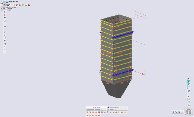
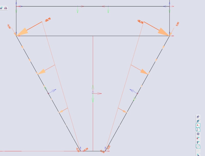
I've calculated the loads, took some time to make an Excel sheet for this stuff, and am now trying to apply them in my SCIA model. A screenshot below (don't mind the missing stiffeners for the hopper, I've not modelled them yet):
steel-silo_jhceji.jpg


The lateral forces for the walls are pretty straightforward, but the other stuff is still confusing. Now if I would like to add the compression forces from the friction to the walls in a way that they are variable according to the depth on the walls then how would this be done - I mean at the transition between the vertical section and the hopper the force is 22,4 kN/m and at the top it's 0,13 kN/m - if I apply this as variable load in the model I'll get too large net reactions.

The other thing is the vertical pressure p[sub]vf[/sub] - how to add this to the model? Or do the hopper load formulas in sections 6.3.2 and 6.3.3 in the code take that weight into account since p[sub]vf[/sub] is in the formulas for the hopper loads?

UPDATE a few minutes later:
So to check the reactions I added friction forces on the walls as variable free surface loads (not as these compressive line loads) - they just act vertically. I then added the normal and friction forces to two sloped walls of the hopper, since I have a steep wedge hopper. And now the net vertical reaction from all this is 300,33 kN - which corresponds pretty much exactly to the weight and volume of the vertical section of the silo: V=6,415*2,0*2,6=33,36 m³, weight of grain 9 kN/m³ - total weight G=300,24 kN. But where is the weight of the filled hopper taken into account - the hopper has a volume of about 3 m³, so that would be additional 27 kN?

Sorry for the silly questions.
 
It seems like you are on the right track. Though you can probably reduce the number of stiffeners on the top of the hopper as the loads are lower.

nivoo_boss said:
But where is the weight of the filled hopper taken into account - the hopper has a volume of about 3 m³, so that would be additional 27 kN?
Have you included the normal loads in the hopper? In the hoper the sides are no longer vertical so you have a vertical component in the normal pressures.

However, If you are chasing the loads to balance you are not going to get that if you are applying the material factor loads correctly. As the factors for calculating the wall loads are different from the factors calculating the pressure loads. This is deliberate because if you product/wall is low friction your hopper might take 70% of the load. Whereas if you product/wall is high friction your wall might take 70% of the load.

If you follow your calculations through you get 140% of the total load in the vessel. Which is fine for calculating vessel strength. Not fine for calculating the weight of the vessel on the supports.

As I said earlier for bin design I don't bother with calculating wall friction or vertical loads on my rectangular vessels. Especially if they are top supported like yours seems to be. The stress levels are inconsequential. The normal forces are the ones that will generally govern the design and are all resolved within the bin.

The unresolved vertical forces are simply the weight of the product&bin and will resolve via the supports generally putting only minor loads on the walls.
 
human909 said:
Have you included the normal loads in the hopper? In the hoper the sides are no longer vertical so you have a vertical component in the normal pressures.

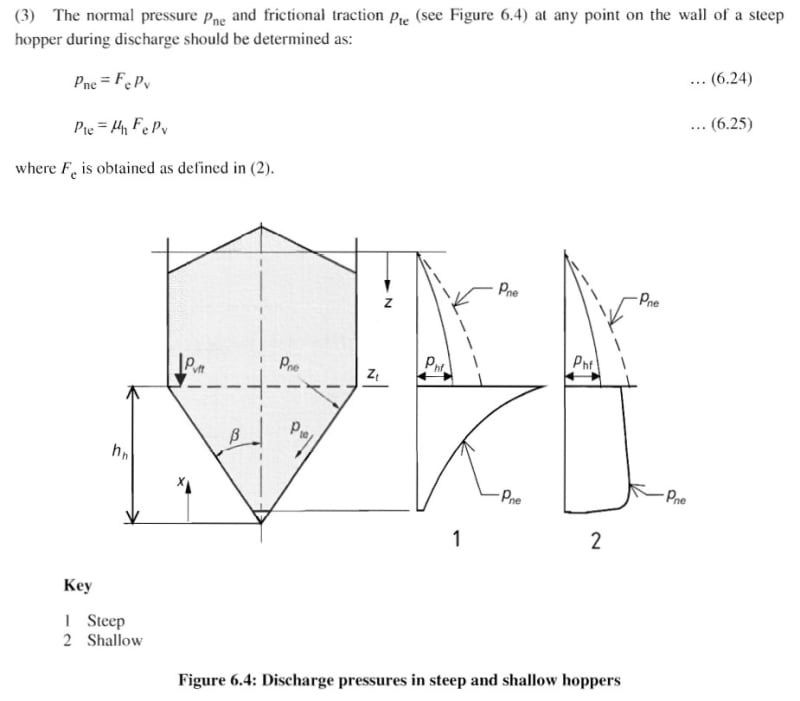
I did, the discharge loads are governing for this case. I used the formulas 6.24 and 6.25 from the code for this:
hopper-discharge_npsycw.jpg


human909 said:
However, If you are chasing the loads to balance you are not going to get that if you are applying the material factor loads correctly. As the factors for calculating the wall loads are different from the factors calculating the pressure loads. This is deliberate because if you product/wall is low friction your hopper might take 70% of the load. Whereas if you product/wall is high friction your wall might take 70% of the load.

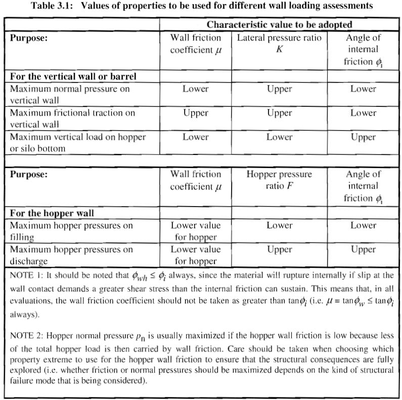
I did use the factors for the wall friction coefficient, lateral pressure ratio and angle of internal friction according to table 3.1.
table_3.1_ya1i91.jpg

The loads applied in the model for case "Maximum hopper pressures on discharge" for the hopper sloped walls:
loads-on-hopper_mhadui.jpg


But I haven't included the third case in the table, which is "Maximum vertical load on hopper or silo bottom" - I do not know how to include this in the model - to what section should I apply this?
 
Hi nivoo_boss. First I'll congratulate you on getting this far. Based on this question and others, you seem a new and youngish engineer who is continually facing problems outside the sphere of knowledge. Normally this goes badly. But you seem to have mostly grasped that aspects involved here and are being quite thorough. So well done. [thumbsup2]

One thing I think you are trying to achieve here is to incorporate all the loads into one model. That is not realistic and not consistent. Though it seems you have done very well to get 90% of the way there. (I generally segregate my models, or only look at normal pressures and ignore vertical pressures.) For large vessels that are bottom supported the normal and vertical loads definitely need to be examined together.

With regard to your question:
nivoo_boss said:
But I haven't included the third case in the table, which is "Maximum vertical load on hopper or silo bottom"

I calculate this value by the following formula:

Code:
Pv{hopper transition-uppervalue} X AREA{hopper transition} + MASS OF MATERIAL IN HOPPER = [b]TOTAL LOAD on HOPPERorSILO BOTTOM[/b]

As already mentioned you'll likely find this load is largely inconsequential. For non circular bins it is mostly about wall pressure and the vertical loads are generally not significant unless it is bottom supported.

If you have anymore questions I am happy to answer them as this is an area that I delve into regularly. A pink star would also be appreciated if you have found my comment helpful. [wink]
 
Thanks! I actually see myself that the normal loads are the ones that govern the design. The other questions are more like just for knowledge.

And a pink star has been awarded :) Though I think it's already a second one for you - I think I added the first one on my phone and perhaps it didn't get awarded in the browser there.
 
[thumbsup][thumbsup2]

Glad to see you are on the right track. And I'm happy to help as you have made it most of the way through you own efforts.

I've spent years doing this stuff. I won't claim to be a total expert but I have many dozens of silos or rectangular bins that are in service.
 
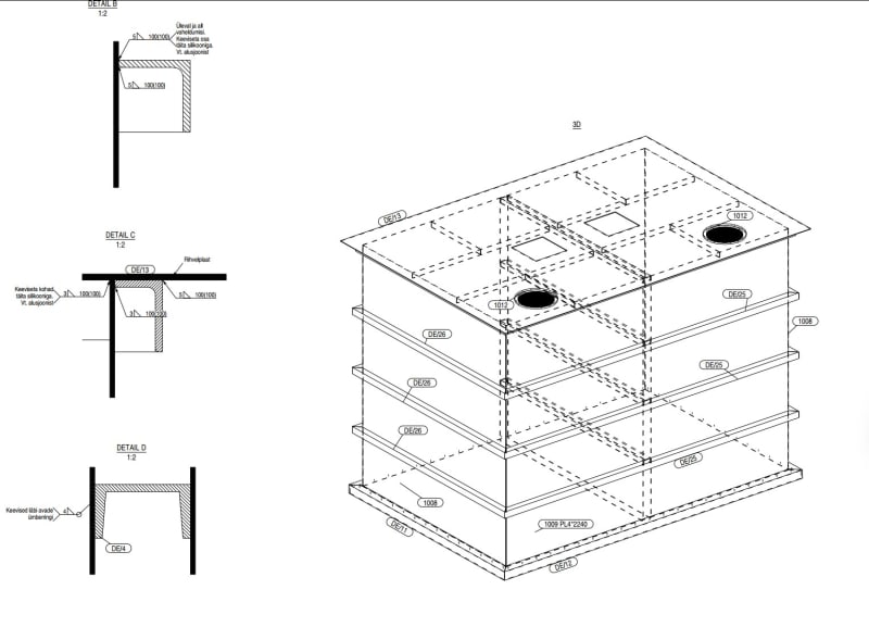
I'll ask a few more questions then :) Can you give some advice on what the most sensible sections to use as stiffeners might be for this kind of silo? I think I'll use 4 or 5 mm steel plates as main walls and some angle sections (currently L70*7) for stiffeners. The silo I'm designing is for a factory that produces like live stock feed pellets - this is a second factory, the first one was built in 2014 on the same property and I worked under an engineer as a draftsman back then. Anyway, the silos there used stiffeners arranged like this:
bin_udtjk3.jpg


The other thing is local deflection of the walls - in EN 1993-4-1 formula 9.10 gives a limit deflection of d[sub]max[/sub]=k[sub]3[/sub]L, where k[sub]3[/sub]=0,05 and L is the shorter dimension of the rectangular plate - which in my case is 2600 mm. So this would mean a limit deflection of 130 mm, which seems way too much. A screenshot from the aforementioned code:
delfection_c5jc4r.jpg
 
nivoo_boss said:
The silo I'm designing is for a factory that produces like live stock feed pellets
I had already figured that our from your previous posts. [wink] I am somewhat an expert in this particular type of manufacturing plant having designed dozens.

nivoo_boss said:
I think I'll use 4 or 5 mm steel plates as main walls
4-6mm would be my recommendation. It is a complicated balance of steel cost vs labour cost. In areas where labour costs are higher then 6mm and fewer stiffeners might be more economic.

You can spend excessive amounts of time trying to optimise a design, it probably isn't worth your time or your clients.

nivoo_boss said:
some angle sections (currently L70*7) for stiffeners.
That probably would work, strength wise. But you have raised deflection issues. But unequal angle say L100×50×6 might do a little better. I haven't done the calculations.

nivoo_boss said:
The other thing is local deflection of the walls - in EN 1993-4-1 formula 9.10 gives a limit deflection of dmax=k3L, where k3=0,05 and L is the shorter dimension of the rectangular plate - which in my case is 2600 mm. So this would mean a limit deflection of 130 mm, which seems way too much. A screenshot from the aforementioned code:
I'd agree that 130mm is "too much". The codes I follow don't dictate deflection and my clients aren't fussy. But I'd be trying to achieve at least half that amount.

Have a look at 100mm or 120mm deep stiffeners to achieve suitable deflection limits.
 
human909 said:
I'd agree that 130mm is "too much". The codes I follow don't dictate deflection and my clients aren't fussy. But I'd be trying to achieve at least half that amount.

Even about 65 mm seems quite a lot to me :). So is it normal that the walls bulge out this much?
 
nivoo_boss said:
Even about 65 mm seems quite a lot to me :). So is it normal that the walls bulge out this much?
I'd agree that 65mm over 2600mm = 1/40 is very much on the high side of what is "acceptable". But who defines what is acceptable? Most of the deflection criteria we are used to as structural engineers relate to human or interior fitout interaction with the deflection. For a bin used for storage none of that applies (for my jurisdiction). If you ensure that your vessel is strong enough nobody will care.

Personally I design my vessels primarily for to suit FACTOR STRENGTH not for deflection. But I make choices to ensure that deflection is minimised by choosing deeper unequal angles. So for you case my design might be fewer stiffeners, 6mm plate and 125 or 150mm unequal angle. This will mean less labour costs and a stiffer bin.

**All the loads I use are factored loads. Either assessing strength or deflection. In reality the actual realised loads are probably going to be half the factored loads.

With regard to real work experience I've run my hand over bins under load though never measure the deflection. At a guess I've seen 50mm. You can see and feel the bulge. But nobody will care as long as the bin is strong enough.
 
PRO TIP:

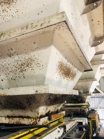
If you are going to overdesign one are. Over design the hopper. The bin itself will hardly get touched. But in MANY cases the hopper is subject to HAMMER RASH.

Viper_20Mine.jpg_vqn6g4.jpg


This is an extremely common scenario in such facilities. Product gets stuck and caked on walls and somebody hits the walls with a hammer. Hence the term.
 
human909 said:
If you are going to overdesign one are. Over design the hopper. The bin itself will hardly get touched. But in MANY cases the hopper is subject to HAMMER RASH.

Thanks for the tip :)
 
Another morning, another questions. Would steel bars (I'm thinking 8x70 mm or something) instead of angle sections for stiffeners be okay as well? The manufacturer didn't like the angle sections too much - they thought painting them would be a bit labour intensive.
 
Yes, flat bar is also quite as it is simpler though less efficient from an engineering perspective.

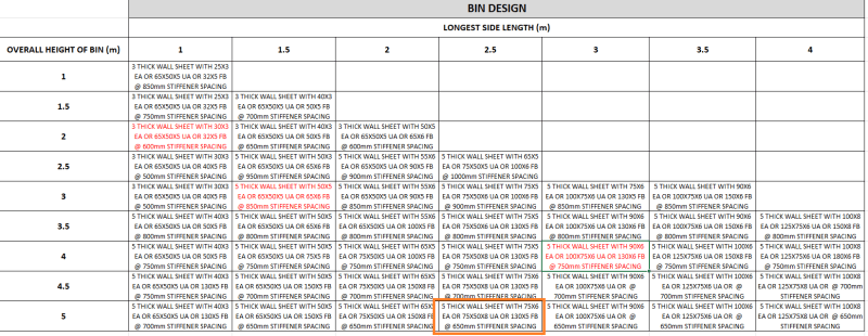
During some idle time I got a junior colleage to create a spreadsheet for this and produce a standard sizing for bins. It was 75% of the way there. I haven't had time to review it.

But this is the output:

(The chart only goes up to 5m bin height but 6m wouldn't be much higher pressure) Also eyeballing some of the values it seems like it might have deflection issues as the spreadsheet criteria was strength only.

temp_pf532l.png
 
nivoo boss said:
But I haven't included the third case in the table, which is "Maximum vertical load on hopper or silo bottom" - I do not know how to include this in the model - to what section should I apply this?

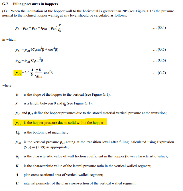
I recommend using the alternate formulas in the Annex G chapters if you want to use Scia or another FEA software:
Schermafbeelding_2024-10-23_142945_kv7upz.png

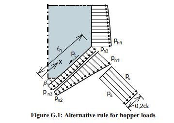
with a clear figure how the forces should be oriented:
Schermafbeelding_2024-10-23_143028_juuy8w.png

Pn1-Pn2 are the forces due to the material in the cilinder
Pn3 are the forces due to the material in the hopper
They are all based on the vertical pressure pvf (which doesn't need to be inputted directly, only if the floor is flat). All the forces that you need to input in your FEA model regarding the hopper are the ones on figure G.1

Hopefully this will help others in the future, I was struggling with the same questions you had and found no answers except this thread, so thanks!
 

Part and Inventory Search

Sponsor